


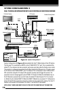
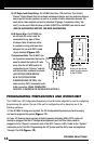
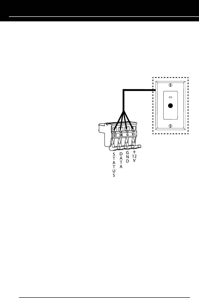
Figure 10.
Home run the sensor
cable from the sensor
to the HT-MSU
(CONTINUED ON NEXT PAGE)
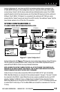
5) 12V Output and Relay Wiring: The HT-MSU has three 12V and three “Dry Contact
Closure” Relay Outputs that can activate mechanical devices such as motorized drapery
and projection screen systems, as well as a number of other automation devices. For
each device these outputs will control, standard 22 gauge 2-conductor cable (“zip-
cord”) can be used. Niles Accessory Cables (FG00724 or FG00933) can also be used
(SEE THE ACCESSORIES SECTION FOR MORE INFORMATION).
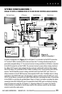
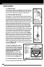
6) IR Sensor Wire: The HT-MSU has
an infrared (IR) sensor input for
connection to any type of Niles
IR sensor. Niles IR sensors utilize
4-conductor wiring and have been
designed for use with CAT-5 cable
(4-pair twisted) (Figure 10).
7) Expansion Cable: The HT-MSU has
an Expansion connection that can be
used to extend the built-in RF radio
away from the HT-MSU and/or for
connection to and “sharing” sources
with future Niles multizone receivers
(SEE SYSTEM CONFIGURATION
#3 IN THE SYSTEM DESIGN
CONSIDERATIONS SECTION). This
cable must be CAT-5 terminated with
RJ45 connectors (T568A TERMINATION
PROTOCOL IS SHOWN IN THE INSTALLATION SECTION 7).
PROGRAMMING PREPARATIONS AND WORKSHEET
The HT-MSU has a PC Configuration/Expansion port on the bottom edge that is used for configuring
(programming) the system. The use of this port for configuration will be based on one of the
following scenarios:
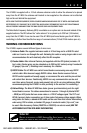
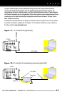
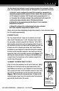
1) If the HT-MSU is being used by itself, the PC Configuration/Expansion port will be empty
and used to program the system (Figure 11).
2) If your iC2 System design involves a Radio Frequency Gateway (RFG), CAT-5 cable will
already be plugged into the PC Configuration/Expansion port and that cable would be
plugged into the “Keypad” connection port of the RFG. Connect a CAT-5 cable to the “System”
connection port of the RFG. Programming the iC2 System and the RFG is now accomplished
“through” the RFG (Figure 12).
16