


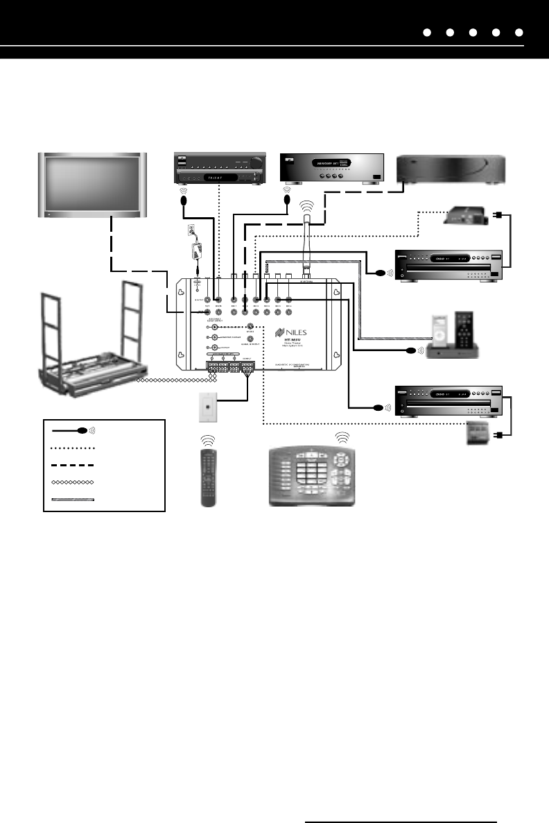
Flat Panel Display HT Receiver Satellite Receiver Media Server
DVD Player
Portable Docking Station
CD Disc Changer
iC2 Remote
CS12V
AC-3
RF ZigBee
Antenna
HT-MSU
12 V DC Power
Supply
Motorized Lift
Remote
WS110
Flasher
12 Volt
RS232
2 Conductor
Video Synch
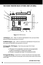
Figure 5.
System Configuration 1
NILES AUDIO CORPORATION – 1-800-BUY-HIFI – 305-238-4373
11
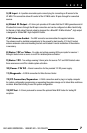
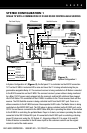
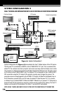
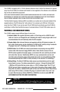
SYSTEM CONFIGURATION 1
SINGLE TV WITH A COMBINATION OF IR AND RS232 CONTROLLABLE SOURCES
In System Configuration #1 (
Figure 5
), the flat panel TV is controlled via the RS232 connection
TV/7 on the HT-MSU. A motorized lift to raise and lower the TV is being activated using the pro
-
grammable assignable Relay #1. The surround receiver is being controlled via IR flasher connected
to the RCV/8 connection on the HT-MSU. The surround receiver’s power status is being monitored
by a Niles 12V DC power supply plugged into the receiver’s switched AC outlet and then plugged
into RCV/8 Status 12V connection on the HT-MSU. In addition to the TV and receiver, there are five
sources. The DSS Satellite receiver is being controlled via IR from the IR SRC1 port. There is no
status connection to the HT-MSU because it has separate On/Off codes. The Media Server is being
controlled via the RS232 SRC2 port. The DVD player is being controlled via the IR SRC3 port, and a
CS12V Current Sensor connected to the SRC3 Status RCA jack is providing the status. IR connected
to the IR SRC4 is controlling the portable Music Player in its dock, and video is providing the status
connected to the SRC4 Status RCA jack. IR connected to the IR SRC5 port is controlling a latching
power CD player and, using the 12V Output # 1, triggering a Niles AC-3 to power it On and Off.
A Niles IR sensor is connected to the IR sensor input so the customers can still use the original
remote to control the media server.
D