


©
National Instruments Corporation I-1 VXI-SC-1102/B/C User Manual
Index
Numbers
+5 V signal (table), 3-3
A
address handler, 4-2
analog circuitry, 4-3 to 4-4
analog input channels, 4-3
analog output, 4-4
analog input specifications, A-1 to A-4
amplifier characteristics, A-2
dynamic characteristics, A-2 to A-3
input characteristics, A-1
transfer characteristics, A-1 to A-2
analog output, 4-4
B
bulletin board support, C-1
C
calibration, 5-1 to 5-4
equipment requirements, 5-1 to 5-2
gain and offset calibration, 5-2 to 5-4
overview, 5-1
sample program, B-1 to B-4
CGND signal (table), 3-3
CH31- through CH0- signals (table), 3-3
CH31+ through CH0+ signals (table), 3-3
channel input signal connections, 3-3 to 3-4
common-mode input signal range,
3-3 to 3-4
differential input signal range, 3-3
exceeding input levels and ranges
(warning), 3-4
signal terminals, 3-3
Channel Register, 4-2
CJSENSOR signal
cold-junction sensor connection, 3-6
description (table), 3-3
exceeding overvoltage protection
(warning), 3-6
cold-junction sensor connection, 3-6
common-mode input signal range, 3-3 to 3-4
ComponentWorks application software, 1-4
Configuration Register, 4-2
current-loop receivers, installing, 2-3
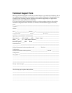
customer communication, xii, C-1 to C-2
D
differential input signal range, 3-3
digital control circuitry, 4-2 to 4-3
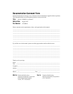
documentation
conventions used in manual, x to xi
National Instruments documentation,
xi to xii
organization of manual, ix to x
related documentation, xii