


©
National Instruments Corporation 4-1 VXI-SC-1102/B/C User Manual
Chapter
4
Theory of Operation
This chapter contains a functional overview of the VXI-SC-1102/B/C
submodules and explains the operation of each functional unit.
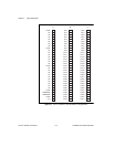
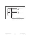
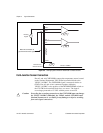
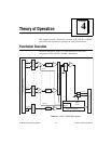
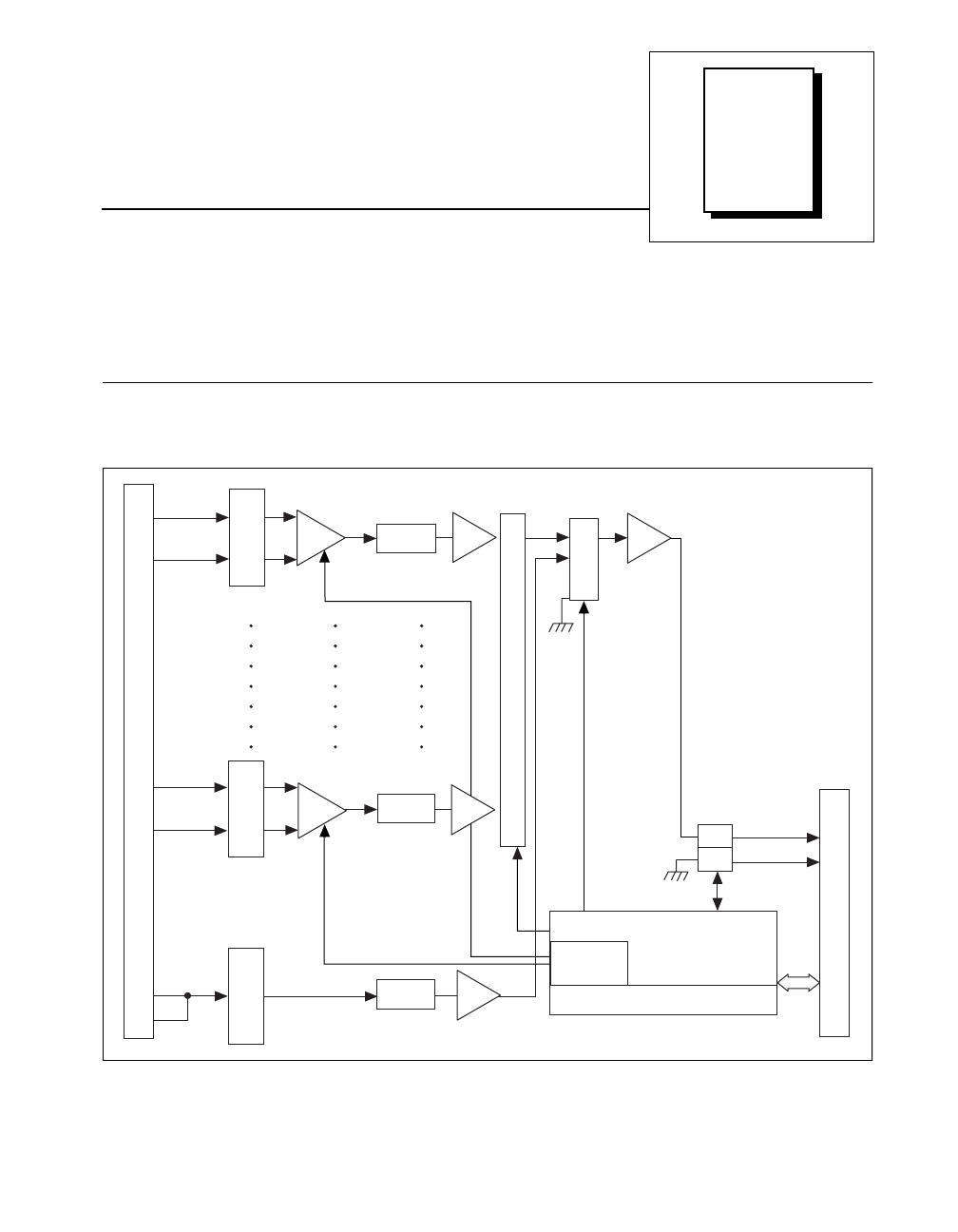
Functional Overview
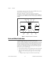
The block diagram in Figure 4-1 illustrates the key functional
components of the VXI-SC-1102/B/C submodules.
Figure 4-1.
VXI-SC-1102/B/C Block Diagram
Front Signal Connector
CH 0 +
Gain 0
CH 0 –
CH 31+
CH 31 –
Lowpass
Filter
Digital
Control
Calibration EEPROM
Lowpass
Filter
Lowpass
Filter
CJSENSOR
Gain 31
Gain
Register
Connector to Carrier Module
Switch
Analog Bus +
Switch
Analog Bus -
32-to-1 Mux
Inst.
Amp
+
Buffer
Mux
Input Protection
and Lowpass Filter
Inst.
Amp
+
Buffer
Buffer
Buffer
–
–
Input Protection
and Lowpass Filter
Input Protection
and Lowpass Filter