


Chapter 4 Theory of Operation
VXI-SC-1102/B/C User Manual 4-2
©
National Instruments Corporation
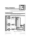
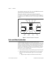
The major components of the VXI-SC-1102/B/C submodules are as
follows:
• VXIbus interface
• Digital control circuitry
• Analog circuitry
The VXI-SC-1102/B/C submodules consist of 32 multiplexed input
channels, each with a software-programmable gain of 1 or 100. Each
input channel has its own lowpass filter. The VXI-SC-1102/B/C
submodules also have digital control circuitry for automatic control of
channel scanning, temperature sensor selection, and gain selection.
VXIbus Interface
The VXI-DAQ module controls the VXI-SC-1102/B/C over the
VXIbus. The VXI-SC-1000 carrier module serves as an interface from
the VXI-SC-1102/B/C submodules to the VXIbus.
Digital Control Circuitry
The digital control circuitry consists of the address handler and the
following registers: Module ID, Configuration, Status, EEPROM, Gain,
and Channel. The address handler controls which register is being
addressed. The Module ID Register contains a code unique to each type
of VXI-SC-1102/B/C submodule:
♦ VXI-SC-1102—The Module ID is 42 decimal.
♦ VXI-SC-1102B—The Module ID is 43 decimal.
♦ VXI-SC-1102C—The Module ID is 63 decimal.
The Configuration Register configures the VXI-SC-1102/B/C
submodules for the desired scanning mode and connection to the rear
signal connector. The Status Register indicates whether the input
channels have settled after a change in the gains. The EEPROM
Register is the address for interfacing with the submodule’s EEPROM,
which contains calibration information. The Gain Register selects
between gains of 1 or 100 for each of the 32 channels. The Channel
Register selects a channel for a single measurement or a start channel
for a scan. Refer to Software Programming Choices in Chapter 1,