


Chapter 4 Theory of Operation
©
National Instruments Corporation 4-3 VXI-SC-1102/B/C User Manual
Introduction, of this manual to learn about options for programming the
control circuitry.
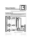
Analog Circuitry
The analog circuitry per channel consists of a lowpass filter and an
amplifier with a software-selectable gain of 1 or 100. The CJSENSOR
channel also has a buffered lowpass filter but has no amplifier. The
channels and CJSENSOR are multiplexed to a single output buffer.
Analog Input Channels
Each of the 32 analog input channels drives a separate amplifier with a
programmable gain of 1 or 100. Then the signal passes through a
three-pole lowpass filter.
Note: Because of the 2 Hz bandwidth of the VXI-SC-1102 input channels, you
must wait approximately 3 s after changing the gains before the channels
settle and you can take an accurate measurement. NI-DAQ automatically
reads the Status Register to determine when the module output has settled.
This time is approximately 100 ms and 1 ms for the VXI-SC-1102B and
VXI-SC-1102C, respectively.
The temperature sensor consists of a thermistor located on a National
Instruments VXI terminal block. The temperature sensor is for
cold-junction compensation of thermocouples. The CJSENSOR
channel also passes through a 2 Hz lowpass filter to reject unwanted
noise. Along with the other 32 input channels, the CJSENSOR is
multiplexed to the output buffer, where it can be read by the VXI-MIO
module.
For a measurement accuracy of 0.012% of full scale, the minimum scan
interval is 3 µs. This is the smallest interval in which you can switch
between analog channels on the submodule and still measure accurate
voltages. The 3 µs scan interval gives you a maximum sampling rate of
333 kHz. Because each VXI-SC-1102/B/C channel contains a lowpass
filter, the 333 kHz sample rate allows you to sample multiple channels
without undersampling any channel.