Chapter 3 Signal Connections
©
National Instruments Corporation 3-3 VXI-SC-1102/B/C User Manual
Signal Descriptions
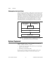
Channel Input Signal Connections
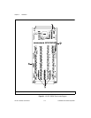
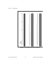
The signal terminals for the positive input channels are located in
column C of the connector. The signal terminal for each corresponding
negative input channel is located in column B of the connector. Each
input goes to a separate filter and amplifier that is multiplexed to the
module output buffer. The terminal block temperature sensor output—
connected to pins A3 and A4 (CJSENSOR)—is also filtered and
multiplexed to the module output buffer.
The differential input signal range of a VXI-SC-1102/B/C input channel
is ±10 V/G, where G is the gain selected on the VXI-SC-1102/B/C input
channel. This differential input range is the maximum measurable
voltage difference between the positive and negative channel inputs.
The common-mode input signal range of a VXI-SC-1102/B/C input
Table 3-1.
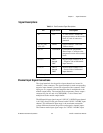
Front Connector Signal Descriptions
Pin Signal Name Description
A1 +5 V +5 VDC Source—Powers the
temperature sensor on the terminal
block. 0.2 mA of source not
protected.
A2, A5, A16,
A24, A32
CGND Chassis Ground—Tied to the
VXIbus chassis.
A3, A4 CJSENSOR Cold-Junction Temperature
Sensor Input—Connects to the
temperature sensor of the terminal
block.
B1–B32 CH31-
through
CH0-
Negative Input Channels 31–0
—Negative side of differential
input channels.
C1–C32 CH31+
through
CH0+
Positive Input Channels 31–0
—Positive side of differential
input channels.
All other pins are not connected.


