Chapter 3 Signal Connections
VXI-SC-1102/B/C User Manual 3-4
©
National Instruments Corporation
channel is ±11 V. This common-mode input range for either positive or
negative channel input is the maximum input voltage (relative to
CGND) that will result in a valid measurement. Each channel includes
input protection circuitry to withstand the accidental application of
voltages up to ±42 VAC peak or VDC.
Warning: Exceeding the input damage level (±42 VAC peak or VDC between input
channels and chassis ground) can damage the VXI-SC-1102/B/C
submodule, the VXIbus, and the VXI-MIO module. National Instruments
is
NOT
liable for any injuries resulting from such signal connections.
Applying a voltage greater than ±42 VAC peak or VDC to the
VXI-SC-1102/B/C is an electrical shock hazard. National Instruments is
NOT
liable for any damages or injuries resulting from such voltage
application.
Note: Exceeding the differential or common-mode input channel ranges results
in a distorted signal measurement.
Ground-Referencing Your Signals
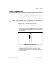
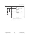
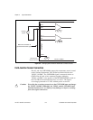
Your input signals can be either ground-referenced, as shown in
Figure 3-2, or floating, as shown in Figure 3-3. Before you connect
your thermocouple or any other signal, determine whether it is floating
or ground-referenced. If it is a floating signal, you must ground-
reference the signal in one of two ways. You can connect the negative
channel input to chassis ground as shown in Figure 3-3 or you can use
the clamping resistors on a VXI-TB Series terminal block. The VXI-TB
Series terminal block may also have a resistor pack for pulling up the
positive inputs for open-thermocouple detection. Consult the terminal
block installation guide for details.
Do not ground signals that are already ground-referenced; doing so will
result in a ground loop, which adversely affects your measurement
accuracy.


