


Index
© National Instruments Corporation Index-3 SC-2040 User Manual
unpacking the SC-2040, 1-4
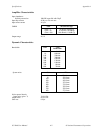
instrumentation amplifiers, 4-3
INT switch position (table), 2-3
J
J11 and J12 connectors. See connectors J11
and J12.
jumpers and switches. See configuration.
L
LabVIEW and LabWindows application
software, 1-2
M
manual. See documentation.
MIO-16E DAQ board, triggering, 4-4 to 4-5
monitoring signal inputs, 3-11
O
operation of SC-2040. See theory
of operation.
output connection, 4-6
output connectors (J11 and J12) signal
summary (table), 3-4 to 3-5
P
parts locator diagram, 2-2
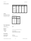
physical specifications, A-3
pin assignments for SC-2040 I/O connectors
J11 and J12 (table), 3-3
power-on sequence, 2-8
power supply
description, 4-6
selecting
procedure for, 2-6
table, 2-3
specifications, A-3
R
register-level programming, 1-4
S
SC-2040
block diagram, 4-2
features, 1-1
I/O connectors (J11 and J12),
(illustration), 3-2
optional equipment, 1-4
required components, 1-1
software programming choices
LabVIEW and LabWindows
application software, 1-2
NI-DAQ driver software, 1-2 to 1-3
register-level programming, 1-4
unpacking, 1-4
shield selection
procedure for, 2-4
table, 2-4
SHLD OFF jumper position (table), 2-4
SHLD ON jumper position (table), 2-4
signal connections
analog signal inputs, 3-7 to 3-1
AC-coupled inputs, 3-10 to 3-11
analog input ranges, 3-10 to 3-11
DC-coupled inputs, 3-7 to 3-8
connections exceeding maximum ratings
(warning), 3-1
digital signal inputs, 3-11
input connectors signal summary
(table), 3-4
monitoring signal inputs, 3-11
other connection considerations, 3-11
output connectors (J11 and J12) signal
summary (table), 3-4 to 3-5
SC-2040 I/O connectors J11 and J12
(illustration), 3-2
signal routing (illustration), 3-6
signal outputs, monitoring, 3-11
software calibration.
See calibration procedures.
software programming choices
LabVIEW and LabWindows application
software, 1-2
NI-DAQ driver software, 1-2 to 1-3