


Signal Connections Chapter 3
SC-2040 User Manual 3-10 © National Instruments Corporation
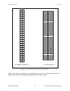
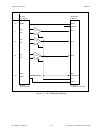
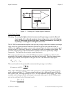
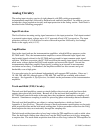
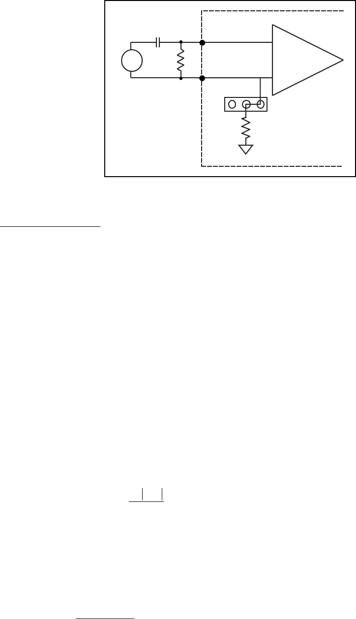
IN-
IN+
100 kΩ
Vin
SC-2040
CH+
CH-
A
A B C
Figure 3-7. Floating AC-Coupled Signal Connection
Analog Input Ranges
Warning: Exceeding the differential and common-mode input ranges results in distorted
input signals. Exceeding the maximum input voltage rating can result in damage
to the SC-2040 board, and the DAQ board. National Instruments is
NOT liable for
any damages resulting from such signal connections.
The SC-2040 instrumentation amplifiers can reject any voltage within their common-mode input
range caused by ground-potential differences between the signal source and the board. In
addition, the amplifiers can reject common-mode noise pickup in the leads connecting the signal
sources to the SC-2040 board. However, you should be careful to minimize noise pickup. The
common-mode rejection of the instrumentation amplifiers decreases significantly at high
frequencies. The amplifiers do not reject normal-mode noise.
The common-mode input range of the SC-2040 instrumentation amplifiers is defined as the
magnitude of the greatest common-mode signal that can be rejected. Thus the common-mode
input range for the SC-2040 depends on the gain and size of the differential input signal:
(V
diff
= V
+
in
- V
-
in
).
The exact formula for the permissible common-mode input range is as follows:
V
cm-allowed
=
±
(12 V -
G V
diff
2
).
Thus, with a differential voltage of 10 V and a gain of G
= 1, the maximum possible common-
mode voltage would be ±7 V. The same range would apply for a differential input of 100 mV
and a gain of 100. The range increases to ±12 V for zero differential input voltage. The actual
common-mode voltage available at the input is measured with respect to the SC-2040 ground,
and can be calculated by the following formula:
V
cm-actual
=
V
+
in
− V
−
in
()
2
.