Chapter 3 Signal Connections
© National Instruments Corporation 3-5 SC-2040 User Manual
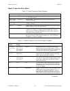
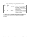
Table 3-3. Output Connectors (J11 and J12) Signal Summary (Continued)
J11 Pin
(50-pin)
J12 Pin
(68-pin)
Signal Name Description
46 38 TRACK*/HOLD
(PFI7/STARTSCAN)
Track-or-hold—This pin, used as an output from the
MIO-16E, controls whether the SC-2040 is in hold
mode or track mode. A high level output from the
DAQ board places the SC-2040 into hold mode, while
a low level returns the SC-2040 into track mode. With
an MIO-16E attached, pin 46 on J11 should be used
for monitoring purposes only.
others others compatibility The remaining pins provide 50 pin compatibility with
the 68 pin MIO-16E. They can be monitored from
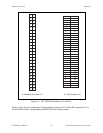
connector J11. Refer to Figure 3-1 for pin locations
and to Chapter 3, Signal Connections, in your MIO-
16E manual for pin descriptions.
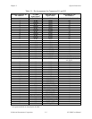
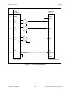
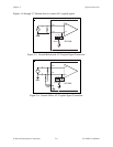
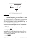
The signals from the SC-2040 screw terminal connectors are connected to the MIO-16E via J12
as shown in Figure 3-2. Observe that the PFI7/STARTSCAN signal returns from the MIO-16E
as a level-sensitive track-and-hold signal to the SC-2040. Notice also that AISENSE is
disconnected.


