Chapter 5 Calibration Procedures
© National Instruments Corporation 5-3 SC-2040 User Manual
Your accuracy needs determine how carefully the offsets need to be calibrated. A typical
requirement might be for total offset referred to output to be less than half of an LSB of the DAQ
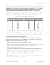
board being used. For example, a 12-bit, 20 V system has a resolution of 20 V/2
12
= 4.88 mV.
Calibration to under 2 mV would thus be sufficient for most applications. The SC-2040 is
factory calibrated to have total offset referred to output of less than 2 mV at low gains.
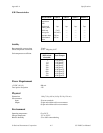
Table 5-1 shows which pots to adjust for each type of offset for each channel and which DIP
switch selects the gain for each channel. Refer to the parts locator diagram in Chapter 2,
Configuration and Installation, to determine the location of each component.
Table 5-1. Calibration Component Identification
Channel Output Offset Adjust Input Offset Adjust Gain DIP Switch
0R1 R4 U2
1 R7 R11 U6
2 R13 R16 U9
3 R18 R22 U14
4 R25 R29 U17
5 R32 R35 U21
6 R37 R41 U24
7 R45 R48 U28
A complicating factor in the calibration of the board is that the output offset is not the same in
track mode as in hold mode. This difference is because of a phenomenon known as hold step, in
which a small amount of charge is transferred to the track-and-hold amplifier hold capacitor
during the transition from track mode to hold mode. This charge transfer slightly changes the
voltage at the output of the track-and-hold amplifier.
The magnitude of the hold step on the SC-2040 is approximately 5 mV, enough to make it
necessary to calibrate output offset in hold mode rather than track mode. You may calibrate
input offset without switching the board to hold mode.
To calibrate the SC-2040 board, the following steps are required:
1. If you are using a rack-mount kit, remove the cover to expose the DIO switches and jumpers.
Connect the board so that the pots and DIP switches are readily accessible.
2. Short each input of the board to ground.
At low gains, more alternatives exist to serve as a short circuit, but at a gain of 500, 1 mV
referred to the output is only 2 µV referred to the input. Thermoelectric effects make it
difficult to keep a short circuit from generating such voltages. The best solution is to use
short lengths of heavy copper wire, and to keep the short away from heat sources.
3. Program the DAQ board to take data in the differential input mode.
The SC-2040 should switch between track mode and hold mode, with the DAQ board
sampling occurring while the board is in hold mode.


