Chapter 4 Theory of Operation
© National Instruments Corporation 4-5 SC-2040 User Manual
. . . . . .
. . . . . .
. . . . . . . . .
. . . . . .
. . . . . . . .
. . . . . .
. . . . . . . . . . .
. . . . . .
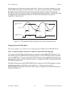
Differential Channel Input
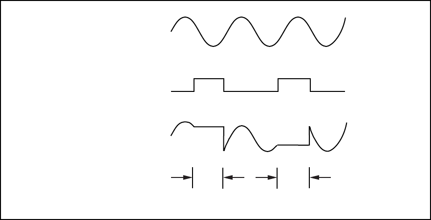
PFI7 (track*/hold)
SC-2040 Channel Output
hold hold track
t
DAQ Conversion
t
DAQ Conversion
(DAQ board is scanning)
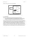
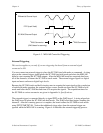
Figure 4-3. MIO-16E Controlled Triggering
External Triggering
This section applies to you only if you are triggering the board from an external signal
connected to J10.
You can connect an external trigger to place the SC-2040 into hold mode on command. A rising
edge on the external trigger signal places the SC-2040 into hold mode and alerts the MIO-16E
board to start scanning the SC-2040 outputs. After the MIO-16E board has acquired data from
all of the channels, it returns the SC-2040 to track mode. The external trigger signal is a digital
input and must conform to digital logic levels.
Because the SC-2040 track-and-hold circuitry must re-acquire the input signals at the conclusion
of each hold mode operation, the external trigger source should not return the SC-2040 to hold
mode until after the SC-2040 has had time to re-acquire the signals. The acquisition times for
the SC-2040 at various accuracies are given in Appendix A, Specifications.
The external trigger is connected directly to signal PFI2 on the DAQ board. A rising edge alerts
the DAQ board to place the SC-2040 into hold mode. The DAQ board then begins scanning the
channels. After the scanning process is complete, the board returns the SC-2040 to track mode
using PFI7/STARTSCAN. Notice that additional rising edges from the external trigger are
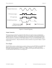
ignored while the MIO-16E is scanning. Figure 4-4 illustrates the external triggering process.


