


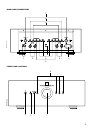


4. AUX INPUT
Input for additional line level input signals or a CD player with no
balanced output. Use a twin RCA-to-RCA lead to connect the
auxiliary unit’s left and right ‘Audio Outputs’ to these inputs.
5. TUNER INPUT
Input for a Tuner or other line-level signal source. Use a twin RCA-to-
RCA lead to connect the Tuner left and right ‘Audio Outputs’ to
these inputs.
6. TAPE, TAPE RECORD
Connections for analogue recording and playback to an audio tape
recorder of any type. Using twin RCA-to-RCA leads, connect the left
and right ‘Audio Outputs’ of the tape machine to the TAPE
connectors for playback and tape monitoring. Connect the left and
right ‘Audio Inputs’ of the tape machine to the TAPE REC connectors
for recording.
7. NAD-LINK IN, OUT
The NAD-Link connector is used to pass commands from the remote
control handset to and from other units fitted with NAD-Link
connectors. This allows centralised control of a complete system or
gives system control from more than one room. To function with
other units, connect the S300’s NAD-Link OUT to the NAD-Link IN on
the other unit. NAD-Link connectors can be daisy-chained, IN to OUT,
so that a whole system can be controlled from the remote control
facilities of one unit.
A single NAD-Link connection from a hi-fi system in a second room
will allow remote control of Multi Room systems.
8. SPEAKERS
Speaker terminals for speakers with an impedance of 4 ohms or
more. Connect the right speaker to the terminals market ‘R +’ and
‘R-’ ensuring that the ‘R+’ is connected to the ‘+’ terminal on your
loudspeaker and the ‘R-’ is connected to the loudspeaker’s ‘-’
terminal.
Connect the terminals marked ‘L+’ and ‘L-’ to the left speaker in the
same way.
Always use heavy duty (16 gauge/2 sq.mm. or thicker) stranded wire
to connect loudspeakers to your S300.
The high current binding post terminals can be used as a screw
terminal for cables terminating in spade or pin connectors or for
cables with bare wire ends.
SPADE CONNECTORS
These should be slotted under the terminal’s screw bushing, which is
then fully tightened. Ensure the connector is tightly secured and
there is no danger of bare metal from spade connectors touching the
back panel or another connector as this may cause damage.
BARE WIRES AND PIN CONNECTORS
Bare wires and pin connectors should be inserted into the hole in the
shaft of the terminal. Unscrew the speaker terminal’s plastic bushing
until the hole in the screw shaft is revealed. Insert the pin or bare
cable end into the hole and secure the cable by tightening down the
terminal’s bushing.
Avoid any danger of bare metal from the speaker cables touching
the back panel or another connector. Ensure that there is only 1/2”
(1cm) of bare cable or pin and no loose strands of speakers wire.
9. GROUND CONNECTOR
The S300 is provided with a GROUND terminal on the rear panel.
This terminal is connected directly to the chassis of the S300. In the
event of radio hum or radio interference, this terminal can be
connected to a ‘true earth’ such as a copper plated rod driven
several feet into the ground.
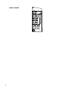
FRONT PANEL CONTROLS
1. POWER
Pressing the POWER button turns the unit On. The blue LED above
the POWER button lights up. After a pause to stabilise all circuits, the
relays click on to open for the signal to the loudspeakers, and the
LED goes off. Pressing the POWER button again will turn the
amplifier Off.
The Power LED is dark when the amplifier is on, and lights up blue
when it is in Standby mode and during the start-up procedure. In
case of a short-circuit of the speaker cables, the LED flashes to
indicate that the protection mode is active.
When you switch on the unit by pressing the POWER button, CD is
always selected as the active input, indicated by the LED above the
CD button lighting up.
Pressing the Standby button on the remote handset while the S300
is On will switch it into Standby mode and the LED above the
POWER button lights up. This shows that power is being supplied to
the S300, but the system is currently in the Standby mode. The next
time you switch the S300 on with the Standby button, the internal
memory selects the input that was active when you switched it to
Standby mode. If you switch off and on with the front panel POWER
button, this memory is deleted, and the unit starts in CD mode.
When in Standby mode, you may press any of the input selector
buttons on the front panel to “wake up” your S300 with that input
active.
CAUTION: When in Standby mode , power is still supplied to your
S300. You should switch it off using the front panel POWER button
when it is not being used for long periods of time.
2. INPUT SELECTORS
These buttons select the active input to the S300 and the signal sent
to the loudspeakers and the Tape Rec output.
LED’s above each button will indicate which input is currently
selected.
CD Selects the (balanced only) CD input (or other line-level source)
connected to the balanced CD sockets as the active input.
VIDEO Selects the VCR (or stereo TV/Satellite/Cable receiver)
connected to the VCR sockets as the active input.
AUX Selects a line-level source connected to the AUX sockets, such
as a CD player without balanced outputs as the active input.
TUNER Selects the tuner (or other line-level source) connected to the
Tuner sockets as the active input.
GB
7