


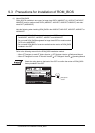
8.3 Wiring Precautions the Part which Matches the EMC Directives
8.3.2 Grounding the ground cable
8 - 18
1
OVERVIEW
2
SYSTEM
CONFIGURATION
3
PERFORMANCE
4
NAMES OF
THE PARTS AND
THEIR SETTINGS
5
ROUGH
PRE-OPERATION
PROCEDURE
6
HANDLING
7
MAINTENANCE AND
INSPECTION
8
EMC DIRECTIVE
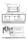
(6) Other PLC and Microcomputer connection
It is necessary for the user to create the cable used to connect GOT with a PLC or a microcomputer
from another company (RS-422 cable or RS-232C cable).
Refer to the GOT-A900 series User’s Manual (Connection System Manual) for information about
the cable creation method.
When connecting GOT to a PLC or microcomputer from another company, configure
the system so that the EMC directive specifications from the connection destination
are applicable.
The contents shown below are a collection of the contents that should be enforced
when made applicable to the EMC directive; however, the final decision to make the
device applicable to the EMC directive and how to make it applicable must be made by
the manufacturer of the machine device.
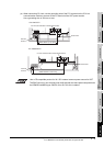
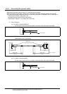
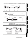
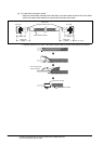
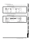
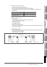
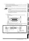
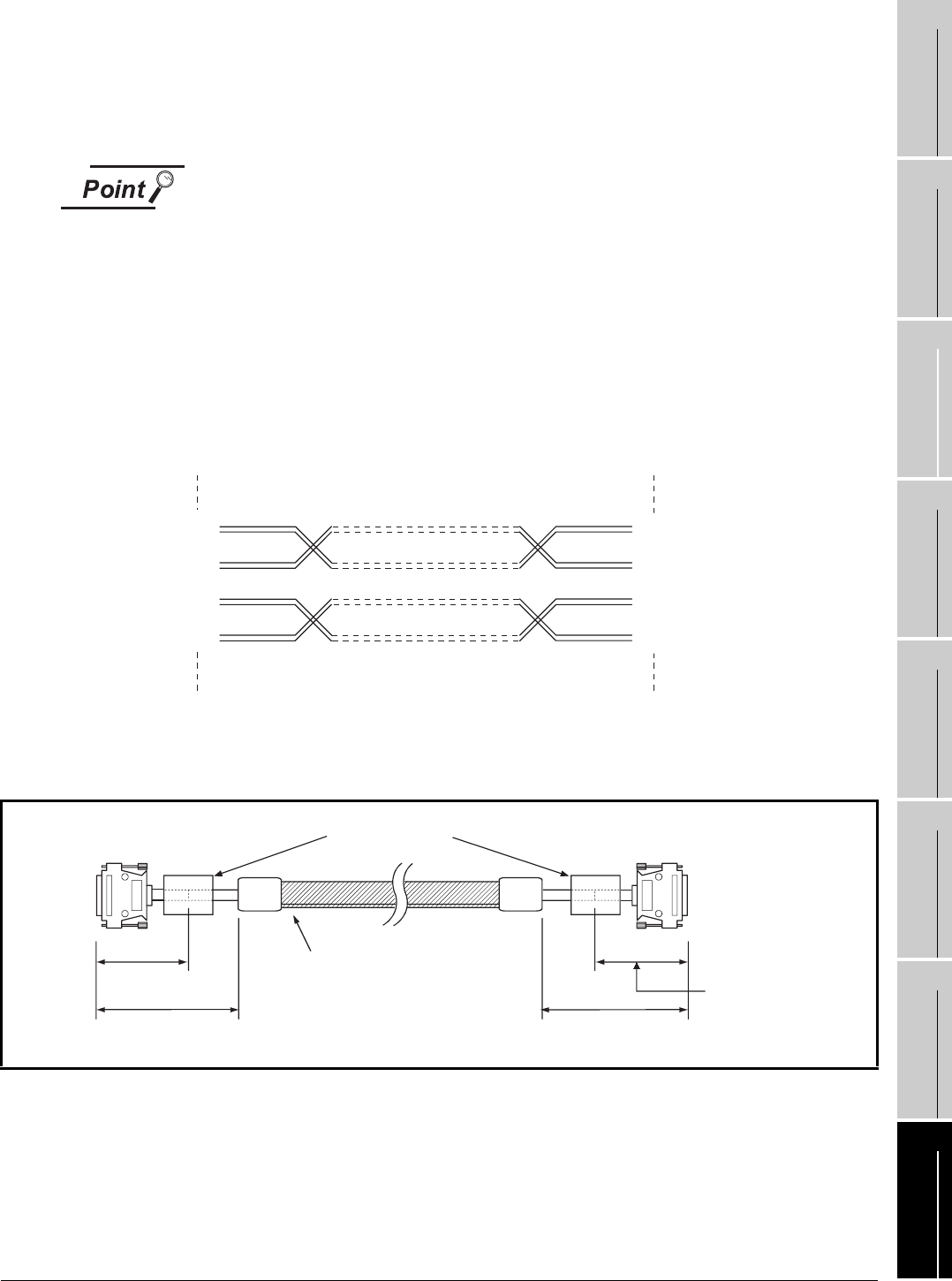
(a) For RS-422 cable
• Each signal wire (excluding SG and FG) should be made into a two power wires and
connected, then twisted.
• Make the SG wire more than two wires and connect.
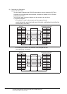
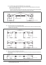
• Wrap the cable shield material around the cable, so that the back aluminum foil side (shield
side) of the cable shield material is exposed at both ends of the cable.
*1 The back aluminum foil side of the cable shield material (shield side) should be exposed. (Refer to Section 8.3.2 (1)
(b))
RDA
RDB
SDA
SDB
RDA
RDB
SDA
SDB
Near the
connection
destination
130
(5.12)
GOT side
Within 250
(9.84)
Ferrite core
(ZCAT3035-1330)
Cable shield material*1
Unit: mm (inch)
Other PLC and
Microcomputer side
Near the connection
destination