


6 - 10
6.1 GOT Main Unit
6.1.3 Wiring method
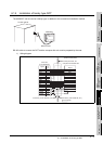
4) Connecting to the GOT Power Section
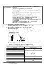
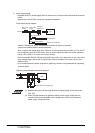
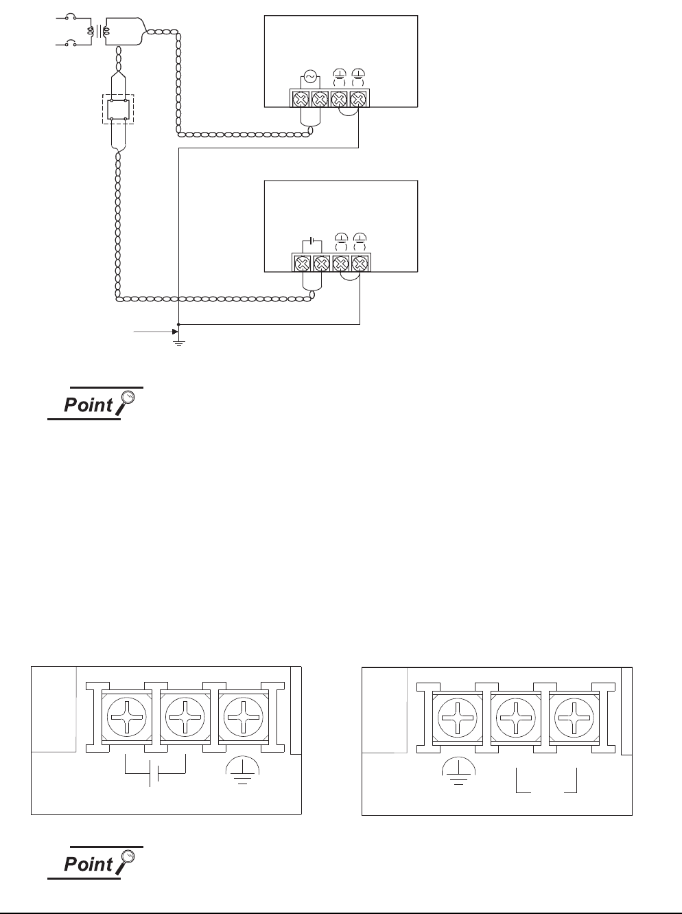
The following diagram shows the wiring example of power lines, grounding lines, etc. to the GOT
power section.
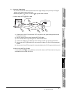
(1) Use the thickest possible (max. 2 mm
2
(14 AWG)) wires for the 100/200 VAC and
24 VDC power cables. Be sure to twist these wires starting at the connection
terminals. To prevent a short-circuit should any screws loosen, use solderless
terminals with insulation sleeves.
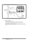
(2) When the LG terminals and FG terminals are connected, be sure to ground the
wires. Do not connect the LG terminals and FG terminals to anything other than
ground. If LG terminals and FG terminals are connected without grounding the
wires, the PLC may be susceptible to noise.
In addition, since the LG terminals have potential, the operator may receive an
electric shock when touching metal parts.
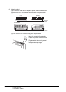
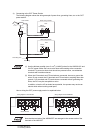
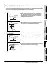
How to wiring the GOT power supply section is explained below.
Note that the terminals of the A956WGOT are arranged in the reverse order of the
terminals of the A95*GOT.
Wiring diagram of the A95*GOT Wiring diagram of the A956WGOT
A
C
AC
DC
100/110VAC
24VDC
Fuse
Grounding wire
Grounding
LG FG
When using 100VAC
LG FG
When using 24VDC
GOT
GOT
INPUT
100-240VAC
INPUT
24VDC
(FG)INPUT 24VDC
(FG)
INPUT
0V
+24V