6 - 20
6.6 Communication Board (A956WGOT only)
6.6.1 Communication board types
6.6 Communication Board (A956WGOT only)
The communication board is used to make the A956WGOT interface compatible with the system to be con-
nected to.
For the details of the connection form, refer to the [GOT-A900 Series User's Manual (Connection System
Manual)].
6.6.1 Communication board types
The following connection board types are available.
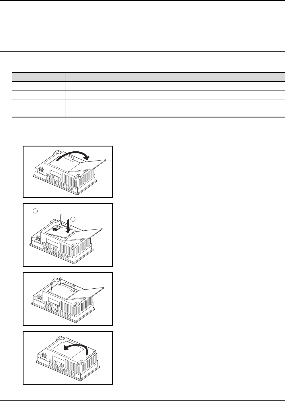
6.6.2 Mounting procedure
Type Description
A9GT-50WQBUSS For bus connection, small connector type (For QCPU (Q mode))
A9GT-50WBUSS For bus connection, small connector type (For A/QnA/Motion controller CPU)
A9GT-50WRS4 For Direct connection to CPU/Computer link connection/Microcomputer connection and RS-422 connection
A9GT-50WRS2 For Direct connection to CPU/Computer link connection/Microcomputer connection and RS-232C connection
1) Open the slot cover on the back of the A956WGOT.
2) Mount the communication board in the slot for mounting a
communication board.
(Align the hole for the attachment screw on the transmission
board with the hole for the attachment screw on the
transmission board of the GOT main module, then attach.)
3) Fix by tightening the mounting screws of the communication
board within the specified torque range.
4) Close the slot cover.
a
b
Insert the communication board
Push down


