


5
ENGLISH
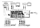
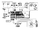
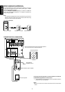
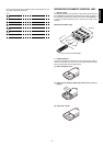
REAR PANEL CONNECTIONS
(SEE PAGE iii.)
All connections to the rear panel should be made with the entire
system powered off.
To avoid errors, it is advisable to connect one cable at a time between
the various components.
A Analog audio inputs for video source
equipment
TV, DVD, VCR1, and DSS/VCR2
Connect each input to the audio outputs of your video source
equipment.
B Analog audio inputs
CD, TAPE, and CD-R/MD
Connect the audio outputs of your source components to the input
jacks on the receiver.
C Analog audio outputs for audio source
equipment
TAPE and CD-R/MD
Connect each output to the audio inputs (REC in) of your recording
equipment.
D FM antenna terminal (75 ohms)
Connect an external FM antenna with a coaxial cable, or a cable
network FM source.
AM antenna and ground terminals
Connect the supplied AM loop antenna. Use the terminals marked
“AM” and “GND”.
The supplied AM loop antenna will provide good AM reception in most
areas.
Position the loop antenna until you hear the best reception.
E Analog audio outputs for video source
equipment
VCR1, and DSS/VCR2
Connect each output to the audio inputs (REC in) of your video
recording equipment.
F Video inputs
TV, DVD, VCR1, and DSS/VCR2
Connect each input to the video outputs of your video source
equipment.
G Video outputs
VCR1, and DSS/VCR2
Connect each output to the video input (REC in) of your video
recording equipment.
H
TV MONI. (VIDEO/S-VIDEO) output jacks
Connect the TV MONI jack to your TV’s video input (VIDEO IN) jack.
You can connect your video equipment with S-VIDEO jacks if
possible, or the composite VIDEO jacks.
You must use the same type of connection from your video
player into the receiver, and out of the receiver into your TV.
Both must be composite video or both must be S-Video. You cannot
convert a signal from one type to the other.
I S-video inputs
DVD and VCR1
Connect each input to the S-video outputs of your video source
equipment.
J S-video outputs
VCR1
Connect each output terminals to S-video input (REC in) of your video
recording equipment.
K AC INLET
Connect to supplied AC cable, and connect to AC power outlet.
SR4200 can be powered by 230V AC only.
L AC OUTLET
Connect the power cables of components such as a DVD or CD player
to this outlet.
Caution:
In order to avoid potential turn-off thumps, anything plugged in
here should be powered up BEFORE the SR4200 is turned on.
M DIGITAL outputs
Optical and Coaxial
Connect digital input of your digital recording equipment.
N DIGITAL inputs
Dig.1, 2 (Optical) and Dig.3 ,4 (Coaxial)
Connect each input to the digital output of your equipment.
Use the system setup menu to assign digital input to appropriate
source. (see page. 11)
Note :
Do not connect for LD player’s RF out, If you want to decode this
type of signal, an external demodulator must be used.
o SPEAKER terminals
FRONT Left & Right speakers output terminals
Connect to the front left & right speakers.
CENTER speaker output terminals
Connect to the center speaker.
SURROUND Left & Right speakers output terminals
Connect to the surround (rear) left & right speakers.
P SUB WOOFER output jack
Connect to the input jack(s) of the power amplifier for subwoofer
channel or powered subwoofer.
Q PRE OUT jacks
Jacks for Front - L/R, Center and Surround.
Use these jacks for connection to an external power amplifier.
R REMOTE CONT. IN/OUT terminals
Connect to a Marantz component equipped with remote control (RC-
5) terminals.