


7
English
English
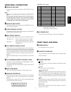
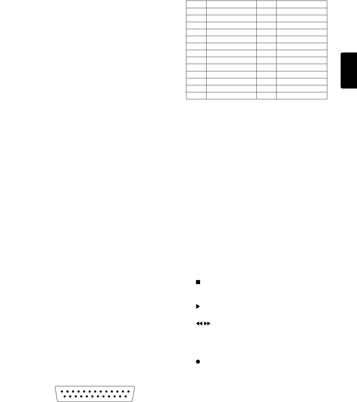
CONTROL I/O Pin assign
Pin No. Function
1 REW A IN
2 REW B IN
3 FF A IN
4 FF B IN
5 PLAY A IN
6 PLAY B IN
7 STOP A IN
8 STOP B IN
9 REC A IN
10 REC B IN
11 REC MUTE A IN
12 REC MUTE B IN
13 A+B REC IN
Pin No. Function
14 NORM IN
15 HIGH IN
16 AUTO REW IN
17 TAPE TIME A IN
18 TAPE TIME B IN
19
COUNTER RESET A IN
20
COUNTER RESET B IN
21 AUTO BIAS A IN
22 AUTO BIAS B IN
23 HIGH OUTPUT
24 GND
25 A+B OUTPUT
¡ All input is active low.
¡ All output is open collector.
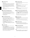
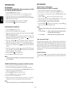
REAR PANEL CONNECTIONS
AA
AA
A
DECK A/B LINE INPUT
These jacks should be connected to LINE OUTPUT of your
source.
Note:
Short pins are installed from the factory in the Deck B IN-
PUT.
The short pins should be removed only if an input source is
connected directly to Deck B. They have been installed to
avoid crosstalk from one deck to the other, in case one deck
is recording and the other deck is playing back.
BB
BB
B
DECK A/B LINE OUTPUT
These jacks should be connected to the LINE INPUT of your
PA or monitoring system.
CC
CC
C LOOP THROUGH A OUTPUT
These jacks output the same signal input to the LINE INPUT
jacks of Well A as they are input.
DD
DD
D INPUT SELECT SWITCH
This switch selects the input mode for the LINE INPUT jacks.
¡ Position A, B : Deck A receives its input from LINE A.
Deck B receives its input from LINE B.
¡ Position A : Both decks receive the same input from
LINE INPUT A.
EE
EE
E RC-5 REMOTE CONTROL JACKS
These jacks are for use with the remote control accessories.
Connect the output of an RC-5 based remote control to the
RC-5 input of the PMD520. The RC-5 output of the PMD520
may be connected to the RC-5 input of other machines for
multiple-machine control from the same remote control ac-
cessory.
Refer to the specifications for the complete RC-5 command
set.
FF
FF
F EXT (EXTENSION) REMOTE CONTROL JACKS
This jack is used to cascade several PMD520s for continu-
ous serial recording and playback.
Connect the EXT OUT jack to the EXT IN jack of the next unit
in the chain.
GG
GG
G MPX FILTER SWICH
When recording FM broadcasts, set this switch to ON.
HH
HH
H PARALLEL CONTROL I/O
These terminals contain a control signal input for almost all
of the operations of the unit and output the A+B and HIGH
signals.
The application range of this unit can be expanded greatly
by using these terminals properly.
II
II
I AC POWER INPUT
Connect one end of the power cord to this receptacle.
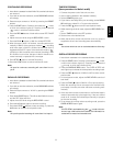
FRONT PANEL FEATURES
qq
qq
q POWER SWITCH
For switching the unit on and off.
ww
ww
w CASSETTE HOLDER A/B
Insert cassettes into these holders with the exposed tape
facing downward.
ee
ee
e CONTROL BUTTONS
STOP
Press this button to cancel any operation modes and to stop
tape travel.
PLAY
Press this button to start playback.
FAST WIND
Press these buttons to fast wind in the direction of the ar-
rows. If the Well is in play mode, these buttons will place the
well in CUE/REVIEW Mode. In CUE/REVIEW mode, if these
buttons are pressed the Well will enter the fast wind mode.
REC
Press this button to enter the REC-PAUSE mode. Press PLAY
to initiate recording. Press this button again to re-enter the
REC-PAUSE mode.
REC MUTE
When in REC-PAUSE mode, press this button to record 3
seconds of no sound.
12345678910111213
141516171819202122232425