


20
4 AC POWER SWITCH AND AC POWER INPUT
An AC power switch is provided which disconnects the PAV from the wall
outlet’s AC power. The PAV is designed to be left in Standby when not in
use, rather than completely “off.” Being in Standby allows it to respond to
commands from the remote control and maintains a stable operating tem-
perature at all times for optimal performance and longevity.
Plug the supplied three-prong power cord into the AC Power Input
recepticle provided before plugging the power cord into the wall. If a
longer AC power cord is required for your application, be sure to use a
three-conductor power cord which conforms to IEC standards.
The Proceed PAV has been safety-tested and is designed
for operation with a three-conductor power cord. Do not
defeat the “third pin” or earth ground of the AC power cord.
Beside the power switch you will find a communications port. This is re-
served for future use (communicating with the PAV's companion piece, the
Digital Surround Decoder). Do not insert anything into this port other than
the communications cable from a “DSD.”
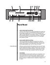
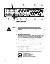
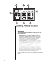
5 REMOTE IR AND REMOTE TURN-ON
A
1
⁄8" “mini” jack labeled remote ir. in the lower right corner of the rear
panel provides direct access to the infrared control circuitry of the PAV. It
may be configured during setup (in an on screen menu) to interpret in-
coming signals in either of two ways:
• Remote: when in Remote mode, the PAV will interpret any com-
mand entering through the remote IR jack as being intended to
affect the remote path only. This feature allows easy access to all
sources connected to the PAV from elsewhere in the house with
the addition of any commercially-available IR repeater.
• Local: when in the Local mode the remote IR jack replaces the
infrared receiver in the main display of the front panel. This
mode is most often used with an IR repeater when the PAV and
other components are placed inside of cabinets (preventing the
normal IR receiver from receiving remote commands). Setting the
remote IR jack to local will disable the IR receiver in the main
display to avoid inconsistent operation which might be caused by
interference between the two. (See Programming the IR Input,
page 47.)
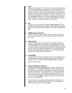
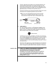
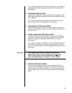
The incoming signal for the remote IR input should conform to widely-ac-
cepted IR repeater standards: that is, the signal present should be between
3-15 volts DC at less than 100 mA current, with a positive tip polarity, as
shown below:
IR input tip polarity
+–
3-15 volts @ less
than 100 mA