


18
cd1 bal/aux
PROC E E D
R
PUSH
21
3
p a v
by MADRIGAL AUDIO LABORATORIES
vcr1 vcr2 tape1 tape2
vcr1 vcr2 tape1 tape2
laser
disc
tv
aux cd2 tuner
center
sub
rear
surround remote main
o u t p u t s
main remote
laser
disc
tv
aux
vcr1 vcr2
main rem
vcr1 vcr2
i n p u t s
remote
i. r. turn-on
PUSH
21
3
PUSH
21
3
PUSH
21
3
1 2 3 4
9 7 6 58
10
11
12
13
12
3
12
3
12
3
12
3
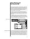
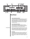
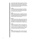
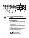
Rear Panel
Caution! Disconnect all associated equipment from the AC mains
BEFORE making any signal connections and applying power
to the PAV.
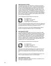
1 SINGLE-ENDED AUDIO INPUTS (8)
Accepts right-channel and left-channel audio signals from source equipment
with single-ended (RCA) outputs. Single-ended audio inputs are provided
for a total of eight components, designated: vcr1, vcr2, tape1, tape2, a
laserdisc player, your tv (or auxiliary component), a cd2, and a tuner. Note
that the video portion of the signal from any video source (VCR, laserdisc,
TV) would be connected on the right side of the rear panel in the Video
Input section. (See below.)
Connect the right-channel and left-channel single-ended outputs of your
various source components to the corresponding inputs on the PAV.
2 BALANCED AUDIO INPUTS (2)
Accepts right-channel and left-channel signals from source equipment with
balanced outputs. Provisions are made for two balanced signals via high
quality XLR connectors, designated cd1 and bal/aux.
The pin assignments of these XLR-type female input connectors are:
Pin 1: Signal ground
Pin 2: Signal + (non-inverting)
Pin 3: Signal – (inverting)
Connector ground lug: chassis ground
PUSH
21
3