19
Owner’s Manual
Owner’s Manual
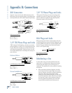
• When connecting an unbalanced output to a bal-
anced input, be sure that the signal high (hot)
connections are wired to each other. The unbal-
anced ground (earth) connection should be wired
to the low (cold) and the ground (earth) connec-
tions of the balanced input. If there are ground-loop
problems, try disconnecting the unbalanced ground
(earth) connection from the balanced input ground
(earth) connection, leaving the unbalanced ground
connected to the balanced input low (cold) con-
nection only.
In some cases, you may have to make up special
adapters to interconnect your equipment. For example,
you may need a balanced XLR female connected to an
unbalanced 1/4" TS phone plug. Many common adapters
can be found at your local electronics supply store.
DB25 Connectors
Analog
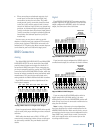
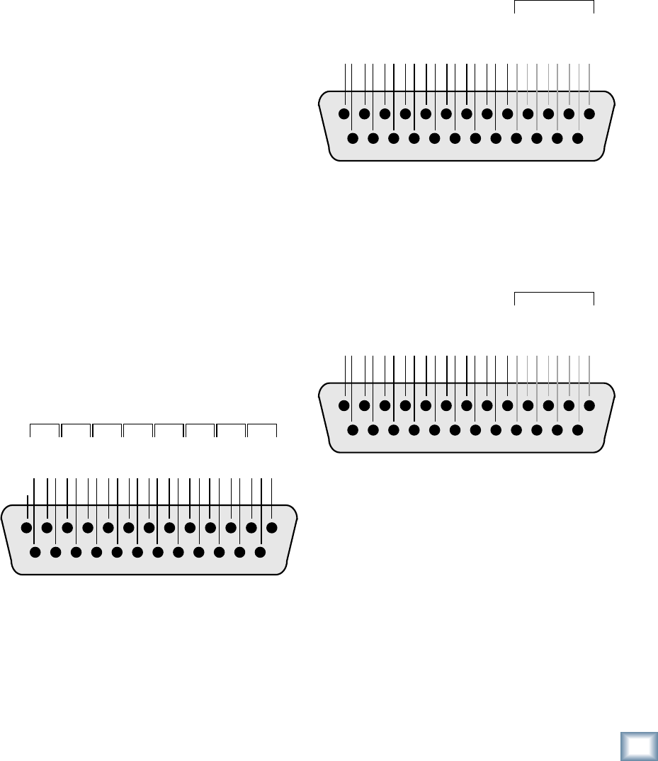
The BALANCED LINE LEVEL INPUTs and BALANCED
LINE LEVEL OUTPUTs on the back of the Onyx 800R
provide balanced inputs and outputs for channels 1-8
on two female DB25 connectors. These connectors are
pin-for-pin compatible with the analog (not TDIF) DB25
connectors found on TASCAM DTRS recorders, which has
become an industry standard for many professional audio
manufacturers. They are also the same pinout as the
analog cards for the Mackie D8B and hard disk recorders.
Each DB25 connector provides eight balanced line-
level inputs or outputs.
12345678910111213
141516171819202122232425
HOT
COLD
GROUND
HOT
COLD
GROUND
HOT
COLD
GROUND
HOT
COLD
GROUND
HOT
COLD
GROUND
HOT
COLD
GROUND
HOT
COLD
GROUND
HOT
COLD
GROUND
CH 1
N/C
CH 2 CH 3 CH 4 CH 5 CH 6 CH 7 CH 8
Several companies make DB25-to-DB25 cables specifi -
cally for audio, with proper shielding to reduce crosstalk
and noise.
DB25 cables that break out to XLR, 1/4" TRS, or TT
connectors for connecting to other mixers or audio gear
are also readily available. See your Mackie dealer for
details.
Digital
The AES/EBU OR S/PDIF OUT connector provides
a digital output for all eight channels. If you have this
output confi gured for AES/EBU, which is a balanced
output, the connector is wired as follows:
12345678910111213
141516171819202122232425
CH 1/2 IN+
CH 1/2 IN–
CH 3/4 IN+
CH 3/4 IN–
CH 5/6 IN+
CH 5/6 IN–
CH 7/8 IN+
CH 7/8 IN–
CH 1/2 OUT+
CH 1/2 OUT–
CH 3/4 OUT+
CH 3/4 OUT–
CH 5/6 OUT+
CH 5/6 OUT–
CH 7/8 OUT+
CH7/8 OUT–
SHIELD
SHIELD
SHIELD
SHIELD
NC
SHIELD
SHIELD
SHIELD
SHIELD
INPUTS NOT
USED ON
ONYX 800R
(110 Ω TERMINATION)
If you have this output confi gured for S/PDIF, which is
an unbalanced output, the connector is wired as follows:
12345678910111213
141516171819202122232425
NC
NC
NC
NC
NC
NC
NC
NC
CH 1/2 OUT
CH 1/2 GND
CH 3/4 OUT
CH 3/4 GND
CH 5/6 OUT
CH 5/6 GND
CH 7/8 OUT
CH 7/8 GND
SHIELD
SHIELD
SHIELD
SHIELD
NC
SHIELD
SHIELD
SHIELD
SHIELD
INPUTS NOT
USED ON
ONYX 800R
(110 Ω TERMINATION)
If you are using the DUAL WIRE position with the
higher sample rates (88.2 kHz and up), the same
cabling that you use for the SINGLE WIRE position will
work as long as you have it connected to another device
using the same method.
Note: A variety of alternate pin-out confi gurations
have been developed by various manufacturers for the
AES/EBU DB25 interface. Make sure the device you are
connecting to has the same pin-out confi guration as the
Onyx 800R. If not, you will need to make a conversion
cable so the signals arrive at the correct pins on the
receiving end of the cable.
Analog DB25 Line-Level Input and Output
Digital DB25 AES/EBU Output
Digital DB25 S/PDIF Output


