13
Owner’s Manual
Owner’s Manual
SIDE MID
OPTICAL OUT
88.2/
96kHz
176.4/
192kHz
44.1/48kHz
1-8 1-81-4 5-8
1-2
3-4
ANALOG MICROPHONE PREAMP WITH 192kHz DIGITAL OUTPUT
BALANCED LINE LEVEL
INPUT
BALANCED LINE LEVEL
OUTPUT
AES/EBU OR S/PDIF OUT
AES/EBU = 110Ω / PRO
SPDIF = 75Ω / CONSUMER
~
100-240 VAC
50-60Hz 105W
87654321
110Ω
75Ω
NORMAL
MID/SIDE
PRO
CONS
DUAL WIRE
SINGLE WIRE
O
N
Y
X
M
I
C
P
R
E
O
N
Y
X
M
I
C
P
R
E
O
N
Y
X
M
I
C
P
R
E
O
N
Y
X
M
I
C
P
R
E
O
N
Y
X
M
I
C
P
R
E
O
N
Y
X
M
I
C
P
R
E
O
N
Y
X
M
I
C
P
R
E
O
N
Y
X
M
I
C
P
R
E
MID/SIDE
DECODE
TERMINATION
OFF
ON (75Ω)
EXTERNAL
WORD
CLOCK IN
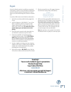
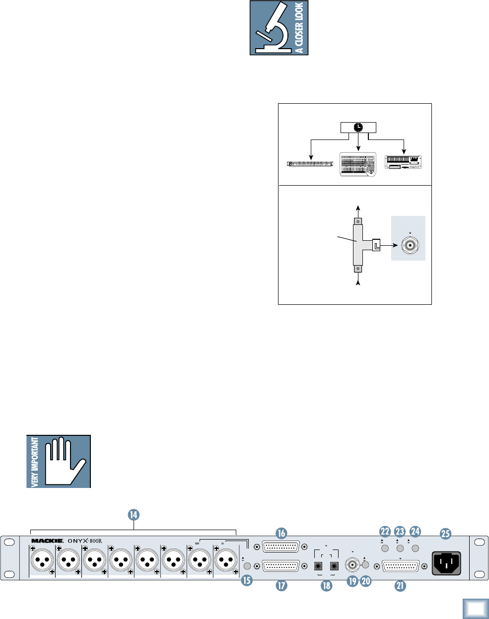
19. EXTERNAL WORD CLOCK IN
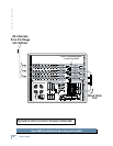
This BNC connector receives word clock from another
device when the SAMPLE RATE selector on the front panel
is set to EXTERNAL. Use this connector when you have mul-
tiple devices that must all operate from a master word clock.
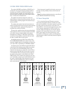
Use 75 Ω coaxial cable when connecting
a word clock to the EXTERNAL WORD
CLOCK IN jack. If there is more than
one device to connect to the word clock,
either use a master word clock distribu-
tion box, which distributes the master word clock to mul-
tiple devices, or use a BNC T-adapter to feed the signal on
to the next device in the chain (see illustrations below).
Word Clock to Other Slaves
(The last device must be terminated)
Onyx 800R
Word Clock
Distribution Amplifier
Word Clock From Master
BNC T-Adapter
EXTERNAL
WORD
CLOCK IN
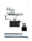
20. TERMINATION
When connecting devices to a word clock, it is impor-
tant that the connection is properly terminated. If an
Onyx 800R is the only device connected to a word clock
output, push in the TERMINATION button to terminate
the connection with 75 ohms impedance.
If two or more Onyx 800Rs (or other devices) are con-
nected to a word clock output in a daisy-chain fashion,
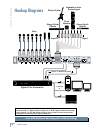
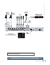
as illustrated in the hookup diagram on page 8, leave the
termination button out on all the Onyx 800Rs except for
the last one in the chain. Remember, the last device in the
chain is the one that should be terminated with 75 ohms.
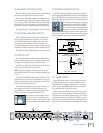
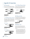
16. BALANCED LINE LEVEL INPUT
This is a DB25 connector, which accepts eight balanced
line-level input signals from almost any source.
This uses the TASCAM standard pin confi guration for
balanced analog audio signals (the same standard used
on the analog cards for the Mackie D8B and Hard Disk
Recorders). Use the LINE switch on the front panel to
select these line-level inputs instead of the MIC inputs.
See Appendix B for a wiring diagram of this connector.
17. BALANCED LINE LEVEL OUTPUT
This is a DB25 connector, which provides balanced
line-level analog outputs for channels 1-8. It uses the
same TASCAM standard pin confi guration as the line-
level inputs, and is designed to connect directly to a
recorder’s analog inputs. These outputs are always active
regardless of what is happening with the digital outputs.
See Appendix B for a wiring diagram of this connector.
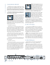
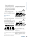
18. OPTICAL OUT
These two Toslink connectors provide a digital output
using the ADAT lightpipe format. At higher sample rates,
the signal is multiplexed using the S/MUX format.
At 32 kHz, 44.1 kHz, and 48 kHz sample rates: All eight
channels are provided on both connectors.
TIP: If you are recording a live show, you can use the
second OPTICAL OUT to make a backup recording, “just
in case.”
At 88.2 kHz and 96 kHz sample rates: Channels 1-4 are
provided on the left connector, and channels 5-8 are pro-
vided on the right connector, as specifi ed by the S/MUX II
protocol for doubled sample rates.
At 176.4 kHz and 192 kHz sample rates: Channels 1-2
are provided on the left connector, and channels 3-4
are provided on the right connector, as specifi ed by the
S/MUX IV protocol for quadrupled sample rates.
If you want to use the higher sample
rates, check your recording device’s
owner’s manual to make sure the opti-
cal inputs support the S/MUX format.


