


7
Section 1: Assembly & Set-up
11/01/12
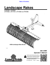
LR0548, LR0560, LR1560, LR1572, LR1584 & LR1596 Landscape Rakes 302-185M
Table of Contents
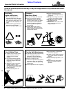
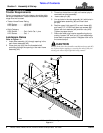
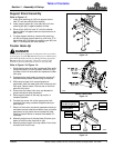
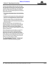
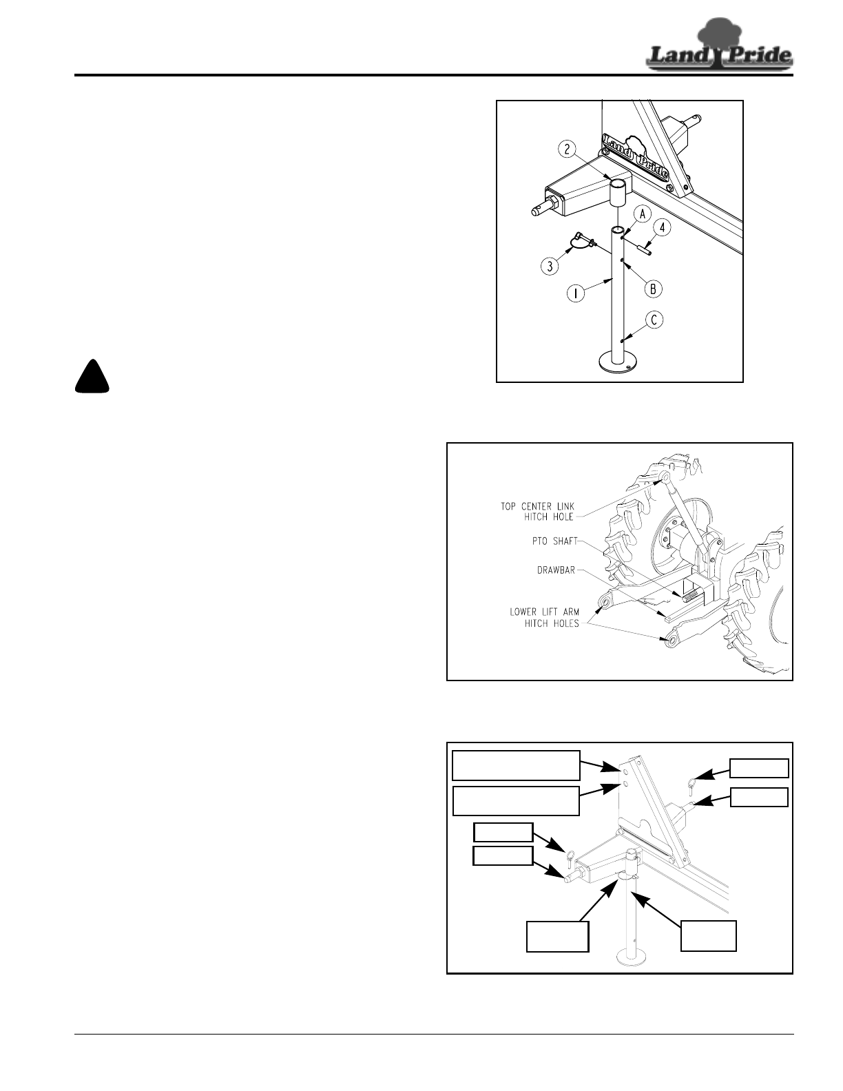
Support Stand Assembly
Refer to Figure 1-2:
1. Insert wire retaining pin (#3) into support stand
hole “B” and secure with wire retainer.
2. Insert support stand (#1) into tube (#2) until wire
retaining pin (#3) is against bottom of tube.
3. Drive roll pin (#4) into hole “A” until pin extends
beyond holes in support stand an equal amount on
both sides.
4. To raise support stand up, remove wire retaining
pin (#3) and raise support stand up until hole “C” is
above tube (#2). Reinsert wire retaining pin (#3) into
hole “C” and secure with wire retainer.
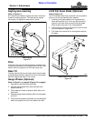
Tractor Hook-Up
!
DANGER
Tractor hook-up to equipment is dangerous and can result in
serious injury or death. Do not allow anyone to stand between
the Landscape Rake and tractor during hook-up operations.
Do not operate the hydraulic 3-Point lift controls while
someone is directly behind the tractor or near the rake.
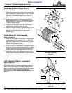
Refer to Figure 1-3 & Figure 1-4:
1. Slowly back tractor up to the Landscape Rake while
using the tractor’s 3-Point hydraulic control to align
the lower hitch link holes with the implement’s lower
hitch pins.
2. Engage tractor park brake, shut tractor engine off,
and remove key before dismounting from tractor.
3. With tractor’s lower hitch arms aligned and
positioned, slide the lower hitch arm holes onto the
hitch pins. Secure lower 3-Point arms on the hitch
pins with linch pins.
4. Ensure that the lower hitch arms are blocked to
prevent excessive side movement.
5. Raise support stand all the way up and pin in
transport position.
6. Connect top center link to the upper pivot hitch
mounting hole using customer supplied clevis pin
and linch pin.
7. Return to the tractor and slowly operate controls up
and down to ensure that the drawbar, tires, and other
equipment on the tractor do not contact the rake
frame and teeth. Move or remove the drawbar if it
interferes.
8. Manually adjust one of the two lower lift arms up or
down to level the rake from left to right.
9. Manually adjust length of the top center link to level
the rake from front to rear.
Support Stand Assembly
Figure 1-2
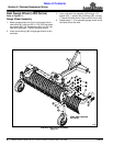
Tractor 3-Point Hitch
Figure 1-3
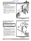
LR05 & LR15 Series 3-Point Hitch
Figure 1-4
35208
23998
25524
Hitch Pin
Hitch Pin
Linch Pin
Linch Pin
Retaining
Pin
Support
Stand
Cat. I Top Center
Link Mounting Holes
LR15 Quick Hitch
Mounting Holes