


1 RECEPTION
2 CONTENTS TS-590S
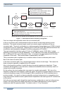
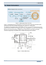
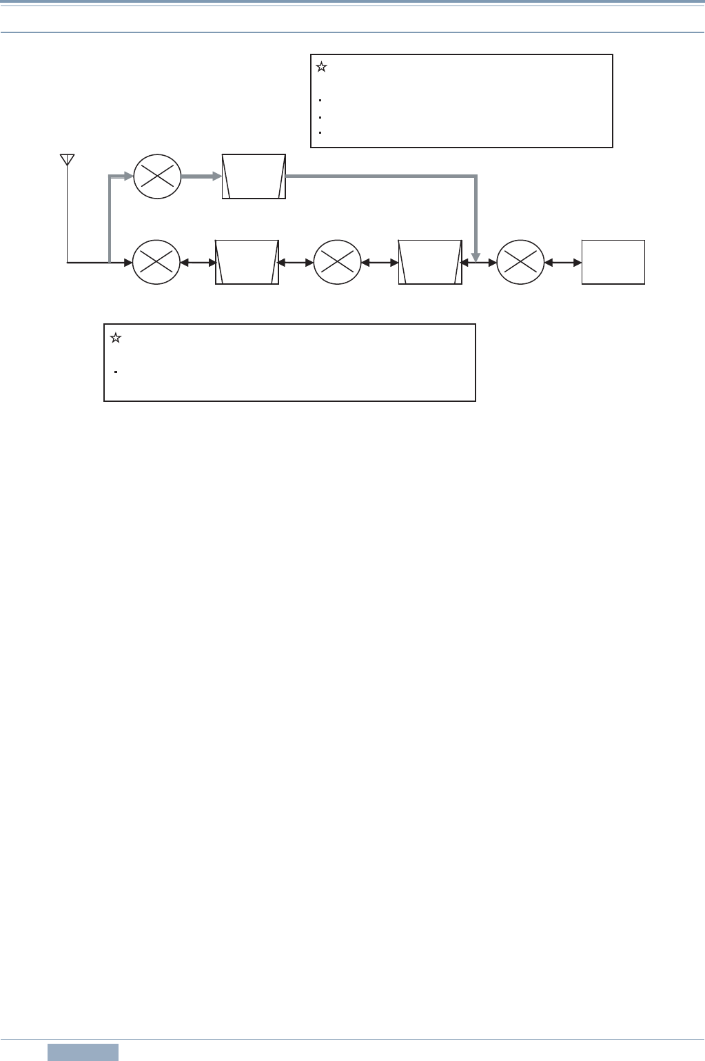
Figure 1-1 Dual-mode Conversion Frequency Configuration
First, let us begin with explanation about the up-conversion path.
In the up-conversion path, double-headed arrows are shown at each stage pointing in both
directions. This means a transmit signal as well as a receive signal is processed in the up-
conversion path. The circuit configuration is a triple-conversion design featuring an IF DSP, a typical
configuration for an HF transceiver. (Replacing the IF DSP with an AF DSP and the third Mixer with
a modulator and demodulator changes it to be the configuration of TS-480S.)
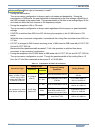
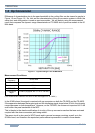
The pass bandwidth of the filter is about 15 kHz at 73.095 MHz, and at 10.695 MHz, it varies
depending on the mode and the RX bandwidth. In CW, SSB and FSK modes, the bandwidth is 2.7
kHz, in AM mode 6 kHz, and in FM mode 15 kHz. (In transmit, the signal passes the 6 kHz filter
regardless of the mode. The final bandwidth is determined by the DSP.)
The up-conversion path is applied only in conditions when no down-conversion path is used.
Next is the down-conversion path.
In the down-conversion path, only a single-ended arrow is shown at each stage. This means the
down-conversion operation is applied only to RX signals.
Also, in the figure the conditions in which the down conversion operates are described. These
conditions are designed to cover the bands, modes and bandwidths that are commonly used in a
contest and on similar occasions.
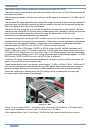
On the surface, the circuit configuration may seem too complex and wasteful. Still, due to the
frequency configuration that focuses on particular points, the general coverage reception across the
continuous frequency range of 30 kHz through 60 MHz covered by the VFO is maintained as on
previous models. As a result, we have successfully produced a transceiver in a competitive price
range that achieves excellent receive performance comparable to the most high-end HF transceivers
on the market.
As for the up-conversion path, though the same frequency configuration is used as in the previous
models, the roofing filters have been improved to have better characteristics to protect against
interference within the pass bandwidth. For details, refer to 1.3 Up Conversion.
2nd Mixer 3rd Mixer 24 kHz73.095 MHz 10.695 MHz1st Mixer
11.374
MHz
500
Hz
2.7 kHz
1st
IF
DSP
Down-conversion path
Double superheterodyne
For 1.8/ 3.5/ 7/ 14/ 21 MHz Amateur bands
If RX passband is 2.7 kHz or less
When receiving in SSB/ CW/ FSK modes
Up-conversion path
Triple superheterodyne
For all the conditions (incl. when transmitting) other than
listed above for down conversion
(Blocks that are not relevant for the explanation of the conversion type are omitted.)