


1 RECEPTION
4 CONTENTS TS-590S
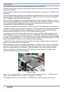
The receiver mixer circuit is a quad mixer consisting of four 2SK1740 JFETs.
The mixer circuit achieves superior characteristics thanks to the revision of I/O port matching and the
optimization of biases.
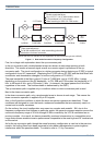
With the signal provided by the first local oscillator, the RX signal is converted to 11.374 MHz (first IF
frequency).
The converted RX signal passes the first roofing filter of pass bandwidth 6 kHz and in the subsequent
stage the signal is moderately amplified by the post amplifier, and sent into the second roofing filter.
Part of the signal is also sent to the noise blanker.
The role of the first roofing filer is to limit the bandwidth for the sake of the noise blanker. We have
selected a pass bandwidth of 6 kHz that does not affect pulse noise. Besides, by setting the intercept
point of the post amplifier higher than that of the mixer, the deterioration of the two-tone
characteristics is minimized within the pass bandwidth.
For second roofing filters, two 6-pole MCFs of 500 Hz and of 2.7 kHz respectively are equipped as
standard at the time of purchase of your transceiver. Which filter is used is automatically determined
according to the final pass bandwidth, i.e. depending on the conditions including the bandwidth
selection made with WIDTH or LO CUT/ HI CUT controls on the front panel.
For example, in CW or FSK mode, if WIDTH is 500 Hz or less, the 500 Hz filter is selected and if
WIDTH is 600 Hz or more, 2.7 kHz filter is selected. In SSB mode, if the difference between the HI
CUT and LO CUT frequencies is 2.7 kHz or less, the 2.7 kHz filter is selected and if the combination
produces exceeds a difference of 2.7 kHz, the up-conversion path is automatically applied. (In SSB-
DATA mode, if WIDTH is 500 Hz or less, the 500 Hz filter is selected.)
In AM and FM modes, because the pass bandwidth of the down conversion path is too narrow, the
signal is received with the up conversion path.
These operations are used in the amateur radio bands of 1.8 MHz, 3.5 MHz, 7 MHz, 14 MHz and 21
MHz, and for other amateur radio bands including WRC bands, and for other frequency ranges of
general coverage receiving, up conversion is used regardless of the mode and pass bandwidth.
(Since this switchover is determined by the CPU taking various conditions into its criteria, the
conversion path cannot manually be selected.)
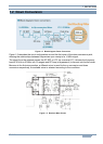
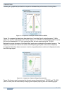
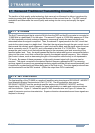
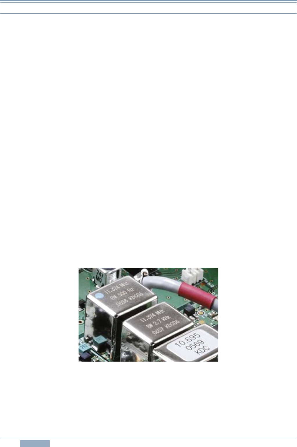
Figure 1-4 MCF
Figure 1-4 is an image of MCFs. From left to right, there is the 500 Hz filter at 11.374 MHz that is
used in down conversion and next is the 2.7 kHz filter at 11.374 MHz.
At the rightmost filter is the 2.7 kHz filter at 10.695 MHz that is used during the up-conversion.