


10
Preparations
L
RL
VIDEO 3VIDEO 2VIDEO 1
S VIDEO
R
A
LC
LR
LR
B
PLAY INPLAY INPLAY INREC OUTPLAY IN
MONITOR
OUT
VIDEO 1
DVD
R
DVD
CD/DVD
OPTICAL
VIDEO 3
OPTICAL
MONITOR
OPTICAL
DIGITAL IN
DIGITAL OUT
VIDEO 2
COAXIAL
COAXIAL DIGITAL
OUT (AUDIO)
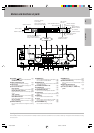
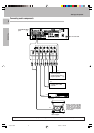
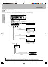
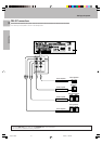
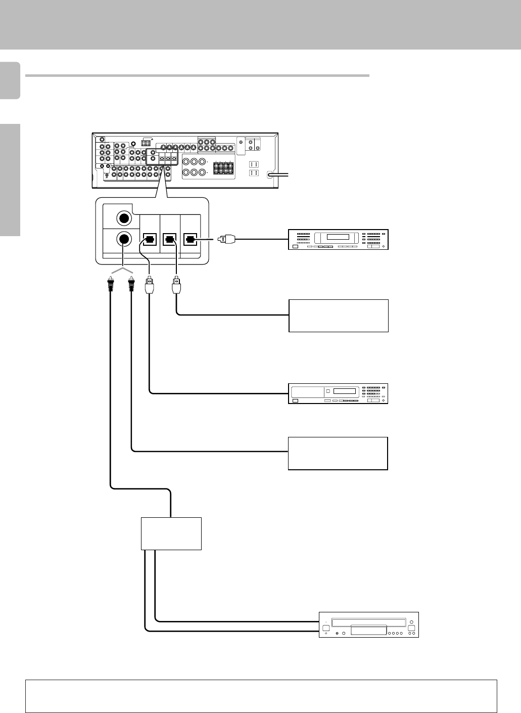
Connect the video signal and
analog audio signals to the VIDEO
2 jacks. (See “Connecting video
components”.) 9
Component with DTS, Dolby
Digital, or PCM OPTICAL
DIGITAL OUT
Connect the video signal and
digital audio signals to the VIDEO
3 jacks. (See “Connecting video
components”.) 9
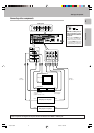
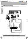
DOLBY DIGITAL RF OUT (AUDIO)
COAXIAL DIGITAL OUT
(AUDIO)
OPTICAL DIGITAL OUT
(AUDIO)
LD player
RF digital
demodulator
(DEM-9991D)
(sold separately
)
PCM OUT
CD player
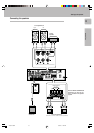
Component with DTS, Dolby
Digital, or PCM COAXIAL
DIGITAL OUT
Optical fiber cable
OPTICAL DIGITAL IN
(AUDIO)
MD player
OPTICAL DIGITAL OUT
(AUDIO)
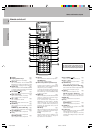
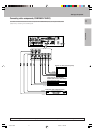
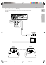
Digital connections
Setting up the system
The digital in jacks can accept DTS, Dolby Digital, or PCM signals. Connect components capable of outputting DTS,
Dolby Digital, or standard PCM (CD) format digital signals.
If you have connected any digital components to the receiver, be sure to read the “Input mode settings” section
carefully. 7
To connect an LD player with a DIGITAL RF OUT, connect the LD player to the KENWOOD RF digital demodulator (DEM-9991D).
Next, connect the DIGITAL OUT jacks of the demodulator to the DIGITAL IN jacks of the receiver.
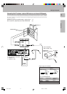
Connect the video signal and analog audio signals to the VIDEO 2 or VIDEO 3 jacks. (See “Connecting video components”.)
*510/07-19/EN 3/15/01, 11:40 AM10