


6
ANTENNA
AM
EXT
AM
LOOP
FM 75
COAXIAL
2
3
1
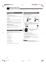
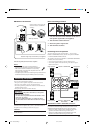
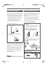
Basic connecting procedure
1 Cut, twist and remove the insulation at the end of
each speaker signal cable (not supplied).
2 Turn the knob counterclockwise.
3 Insert the speaker signal cable.
4 Turn the knob clockwise.
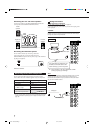
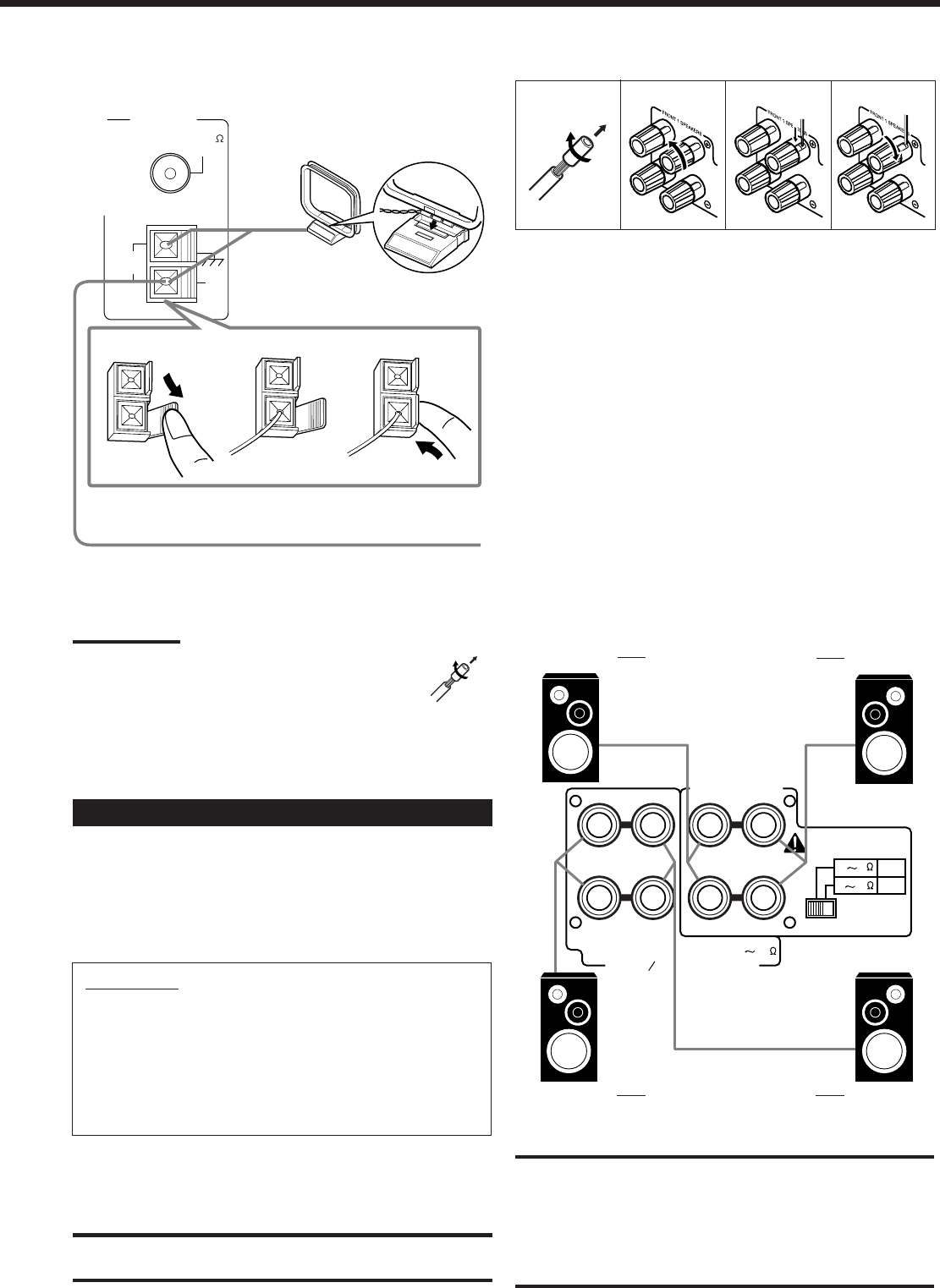
Connecting the front speakers
You can connect two pairs of front speakers — one pair to the
FRONT 1 SPEAKERS terminals, and the other pair to the FRONT
2 / SUB ROOM SPEAKERS terminals.
The speakers connected to the FRONT 2 / SUB ROOM SPEAKERS
terminals can be used as follows:
• As the second front speakers in the main listening room
• As the main speakers in the sub listening room when using the
Multi-room function.
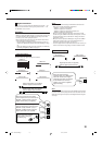
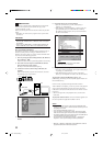
Turn the loop until you have the best reception.
Notes:
• If the AM loop antenna wire is covered with vinyl,
remove the vinyl by twisting it as shown in the diagram.
• Make sure the antenna conductors do not touch any
other terminals, connecting cords and power cord. This
could cause poor reception.
• If reception is poor, connect an outdoor single vinyl-covered wire to
the AM EXT terminal. (Keep the AM loop antenna connected.)
Connecting the Speakers
You can connect the following speakers:
• Two pairs of front speakers to produce normal stereo sound.
• One pair of rear speakers to enjoy the surround effect.
• One center speaker to produce more effective surround effect (to
emphasize human voices).
• One powered subwoofer to enhance the bass.
IMPORTANT:
After connecting the speakers listed above, set the speaker
setting information properly:
• To obtain the best possible Surround and DSP effect in the
main room, see page 29.
• To use the Multi-room function, see “Setting the Front
Speakers Either for the Main Room or Sub-room” on page
27.
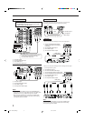
For each speaker (except for a subwoofer), connect the (+) and (–)
terminals on the rear panel to the (+) and (–) terminals marked on
the speakers. For connecting a subwoofer, see page 7.
CAUTION:
Use speakers with the SPEAKER IMPEDANCE indicated by the
speaker terminals.
2
1
3
4
AM Antenna Connections
FRONT 1 SPEAKERS
Left speaker
Right speaker
FRONT 2 / SUB ROOM
SPEAKERS
Left speaker
Right speaker
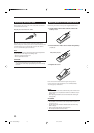
IMPORTANT for FRONT 1 SPEAKERS connection:
To obtain the best possible output power from the receiver, and to
prevent the receiver from being overheated, the receiver has the
SPEAKER LOAD SELECTOR which has to be set as follows:
• Set it to the “HIGH” position when the impedance of the front
speakers connected is within the range of 8 Ω to 16 Ω.
• Set it to the “LOW” position when the impedance of the front
speakers connected is within the range of 4 Ω to 6 Ω.
AM Loop Antenna
Outdoor single vinyl-covered wire (not supplied)
Snap the tabs on the loop into the
slots of the base to assemble the
AM loop.
RIGHT
LEFT
RIGHT
LEFT
RIGHT
LEFT
FRONT 1 SPEAKERS
SPEAKER LOAD SELECTOR
RIGHT LEFT RIGHT LEFT
+
–
+
–
CAUTION : SPEAKER IMPEDANCE
CAUTION :
SPEAKER IMPEDANCE
FRONT 2 SUB ROOM SPEAKERS
816
4 6 LOW
8 16 HIGH
EN01-13.RX-9010VBK[J]f 01.2.15, 0:14 PM6