


40
English
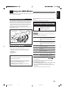
AV COMPU LINK Remote Control System
The AV COMPU LINK remote control system allows you to operate JVC’s video components (TV, VCR, and DVD player)
through the receiver.
This receiver is equipped with the AV COMPU LINK-III, which adds a function to the previous version in order to operate JVC’s video
components through the video components terminals. To use this remote control system, connect the video components you want to operate,
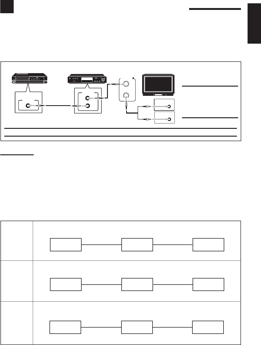
following the diagrams below and the procedure on the next page.
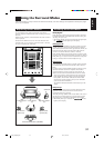
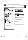
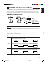
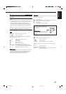
CONNECTIONS 1: AV COMPU LINK Connection
CAUTION:
You can only connect to the TV
with the AV COMPU LINK EX or
AV COMPU LINK-III jack.
DO NOT connect to the TV with
AV COMPU LINK RECEIVER/
AMP jack.
IMPORTANT:
The AV COMPU LINK remote control system cannot control the DBS tuner.
Notes:
• When connecting the receiver and a TV with the AV COMPU LINK EX terminal by using a component video cable, you cannot use automatic
selection of TV’s input mode (see page 41).
• When connecting only the VCR or DVD player to this receiver, connect it directly to the receiver using cables with the monaural mini-plugs.
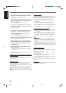
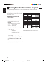
CONNECTIONS 2: Video Cable Connection
This receiver is equipped with three types of the video terminals—S-video, composite video, and component video, and the signals coming
into this receiver through one type of video jacks can output only through the jack of the same type. So you need to connect the VCR and/or
DVD player to the TV using one of the following three ways:
• When using the AV COMPU LINK remote control system, set the component video input for the DVD player and the DBS tuner
correctly (see “Setting the Component Video Input” on page 28); otherwise, the correct input for this receiver will not be selected on the
TV.
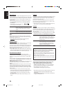
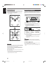
CASE 1 When connecting the source equipment to the receiver through the S-video jacks, connect this receiver
to the TV’s Video Input 1 jack using S-video cables.
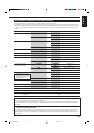
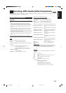
CASE 2 When connecting the source equipment to the receiver through the composite video jacks, connect
this receiver to the TV’s Video Input 2 jack (composite video input) using composite video cables.
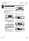
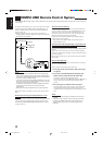
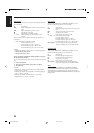
CASE 3 When connecting the source equipment to the receiver through the component video jacks, connect
this receiver to the TV’s Video Input 2 jack (component video input) using component video cables.
Source
equipment
RX-7032VSL
TV
To Video Input 1
S-video cord
S-video cord
Source
equipment
TV
To Video Input 2
Composite
video cord
Composite
video cord
Source
equipment
TV
To Video Input 2
Component
video cord
Component
video cord
AV
COMPULINK-
AV
COMPU LINK
VHS
AV
COMPU LINK
AV
COMPU LINK EX
DVD
AV
COMPU LINK-
ΙΙΙ
VCR DVD player TV
RX-7032VSL
RX-7032VSL
40-50_7032[US]f.pm6 03.3.13, 4:31 PM40