


14
English
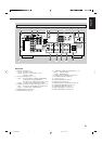
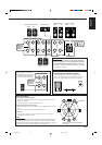
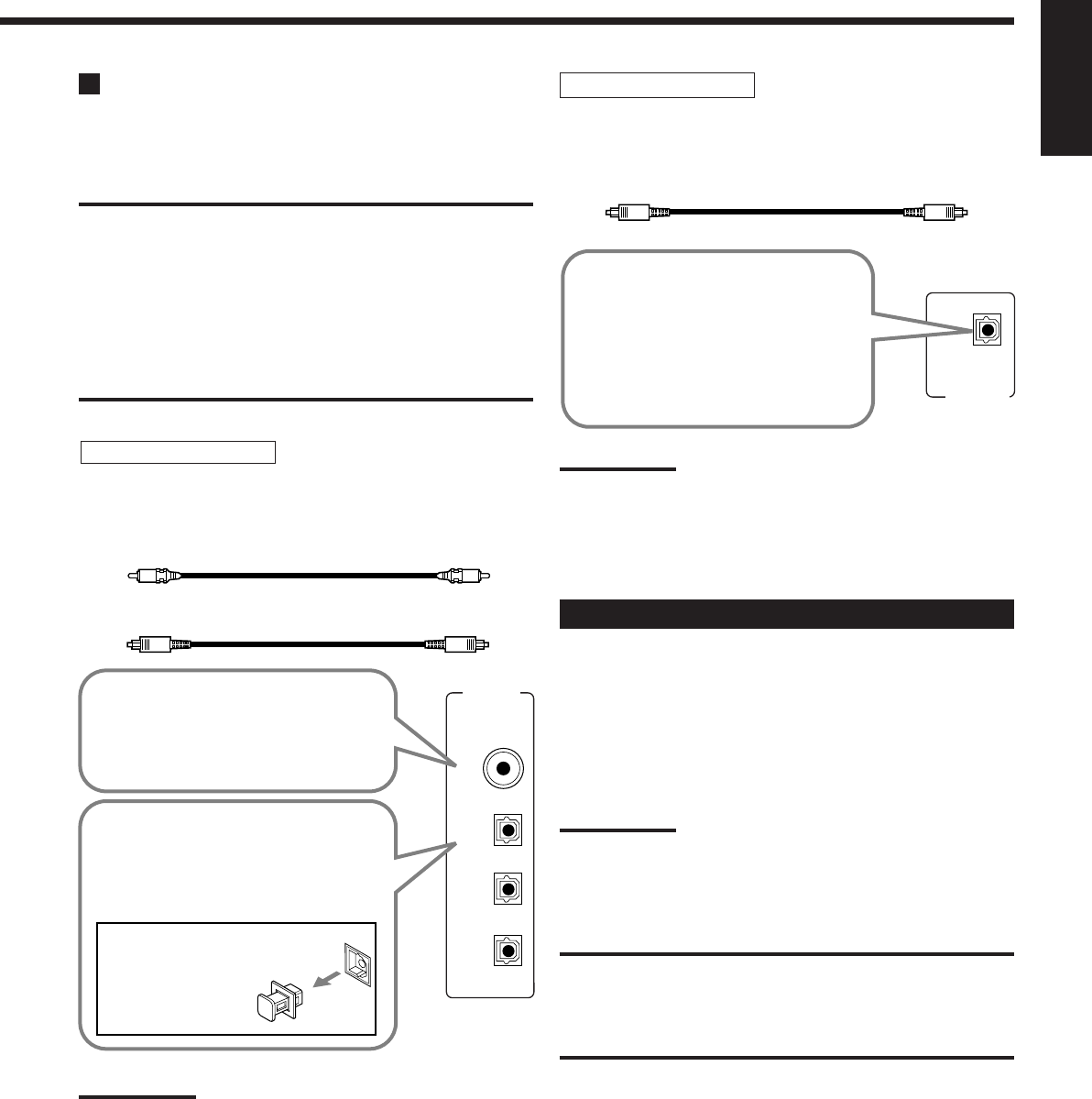
DIGITAL IN
DIGITAL 1 (DVD)
DIGITAL 2 (CD)
DIGITAL 3 (TV)
DIGITAL 4 (CDR)
PCM/ DOLBY DIGITAL
/ DTS
DIGITAL OUT
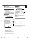
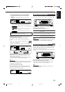
Digital Connections
This receiver is equipped with four DIGITAL IN terminals—one
digital coaxial terminal and three digital optical terminals—and one
DIGITAL OUT (optical) terminal on the rear.
IMPORTANT:
• When connecting a DVD player, digital TV broadcast tuner or DBS
tuner using the digital terminals, you also need to connect it to the
video jacks on the rear. Without connecting it to the video jacks, you
can view no playback picture.
• After connecting the components using the DIGITAL IN terminals,
set the following correctly if necessary.
– Set the digital input (DIGITAL IN) terminal setting correctly. For
details, see “Setting the Digital Input Terminals” on page 28.
– Select the digital input mode correctly. For details, see “Selecting
the Analog or Digital Input Mode” on page 17.
Notes:
• When shipped from the factory, the DIGITAL IN terminals have
been set for use with the following components:
– DIGITAL 1 (coaxial): For DVD player
– DIGITAL 2 (optical): For CD player
– DIGITAL 3 (optical): For digital TV broadcast tuner
– DIGITAL 4 (optical): For CD recorder
• When you want to operate the CD player or CD recorder, using the
COMPU LINK remote control system, connect the target
component also as described in “Analog Connections” (see page
11).
• When you want to operate a DVD player using the AV COMPU
LINK remote control system (see page 40), connect the DVD
player also as described in “Analog Connections” (see page 13).
Digital input terminals
You can connect any digital components having coaxial or optical
digital output terminal.
Digital output terminal
You can connect any digital components which have an optical
digital input terminal.
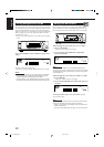
Digital coaxial cable (not supplied)
between digital coaxial terminals
Digital optical cable (not supplied)
between digital optical terminals
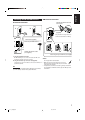
Before connecting a digital
optical cable, unplug the
protective plug.
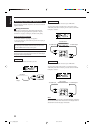
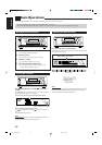
When the component has a digital
optical output terminal, connect it to the
DIGITAL 2 (CD), DIGITAL 3 (TV) or
DIGITAL 4 (CDR) terminal, using a
digital optical cable (not supplied).
When the component has a digital
coaxial output terminal, connect it to
the DIGITAL 1 (DVD) terminal, using a
digital coaxial cable (not supplied).
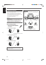
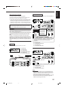
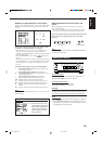
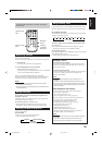
When the digital recording
equipment such as an MD recorder
and CD recorder has a digital
optical input terminal, connecting it
to the DIGITAL OUT terminal
enables you to perform digital-to-
digital recording.
Digital optical cable (not supplied)
between digital optical terminals
Note:
The digital signal format transmitted through the DIGITAL OUT
terminal is the same as that of the input signal. This means that when
the DTS Digital Surround signals are input, the DTS Digital Surround
signals are transmitted.
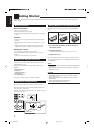
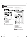
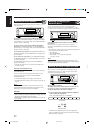
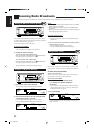
Connecting the Power Cord
Before plugging the receiver into an AC outlet, make sure that all
connections have been made.
Plug the power cord into an AC outlet.
Keep the power cord away from the connecting cables and the
antenna. The power cord may cause noise or screen interference.
Note:
The preset settings such as preset channels and sound adjustment
may be erased in a few days in the following cases:
– When you unplug the power cord.
– When a power failure occurs.
CAUTIONS:
• Do not plug in before setting the VOLTAGE SELECTOR switch on
the rear of the unit and all connection procedures are complete.
• Do not touch the power cord with wet hands.
• Do not pull on the power cord to unplug the cord. When unplugging
the cord, always grasp the plug so as not to damage the cord.
01-14_7032[US]f.pm6 03.3.13, 4:31 PM14