


9
COAXIAL
AM LOOP
ANTENNA
FM 75
AM EXT
VIDEO
AUDIO
COMPONENT VIDEO
SUBWOOFER
OUT
DIGITAL IN
DIGITAL 3
(TV)
DIGITAL 2 (DBS)
DIGITAL 1
(DVD)
DVD
IN
DVD
IN
DVD IN
FRONT
SURR (REAR)
TVVCRDBS
AV
COMULINK-III
ININ
IN
(PLAY)
OUT
(REC)
RIGHT LEFT
SUB-
WOOFER
CENTER
RL
L
R
DBS IN MONITOR
OUT
DBS
IN
VCR
MONITOR OUT
VIDEO
OUT
(REC)
IN
(PLAY)
CENTER
SPEAKER
SURROUND
SPEAKERS
RIGHT LEFT RIGHT LEFT
FRONT
SPEAKERS
CAUTION:
SPEAKER
IMPEDANCE
8
~
16
Y
P
B
P
R
AUDIO
TVVCRDBS
ININ
IN
(PLAY)
OUT
(REC)
L
R
VIDEO
COMPONENT VIDEO
DVD
IN
DVD IN DBS IN MONITOR
OUT
DBS
IN
VCR
MONITOR OUT
VIDEO
OUT
(REC)
IN
(PLAY)
Y
P
B
P
R
LEFT
RIGHT
AUDIO
OUT
TV
S-VIDEO
S-VIDEO
RX-ES1SL
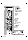
Getting started
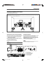
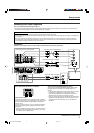
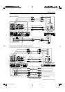
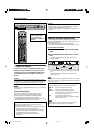
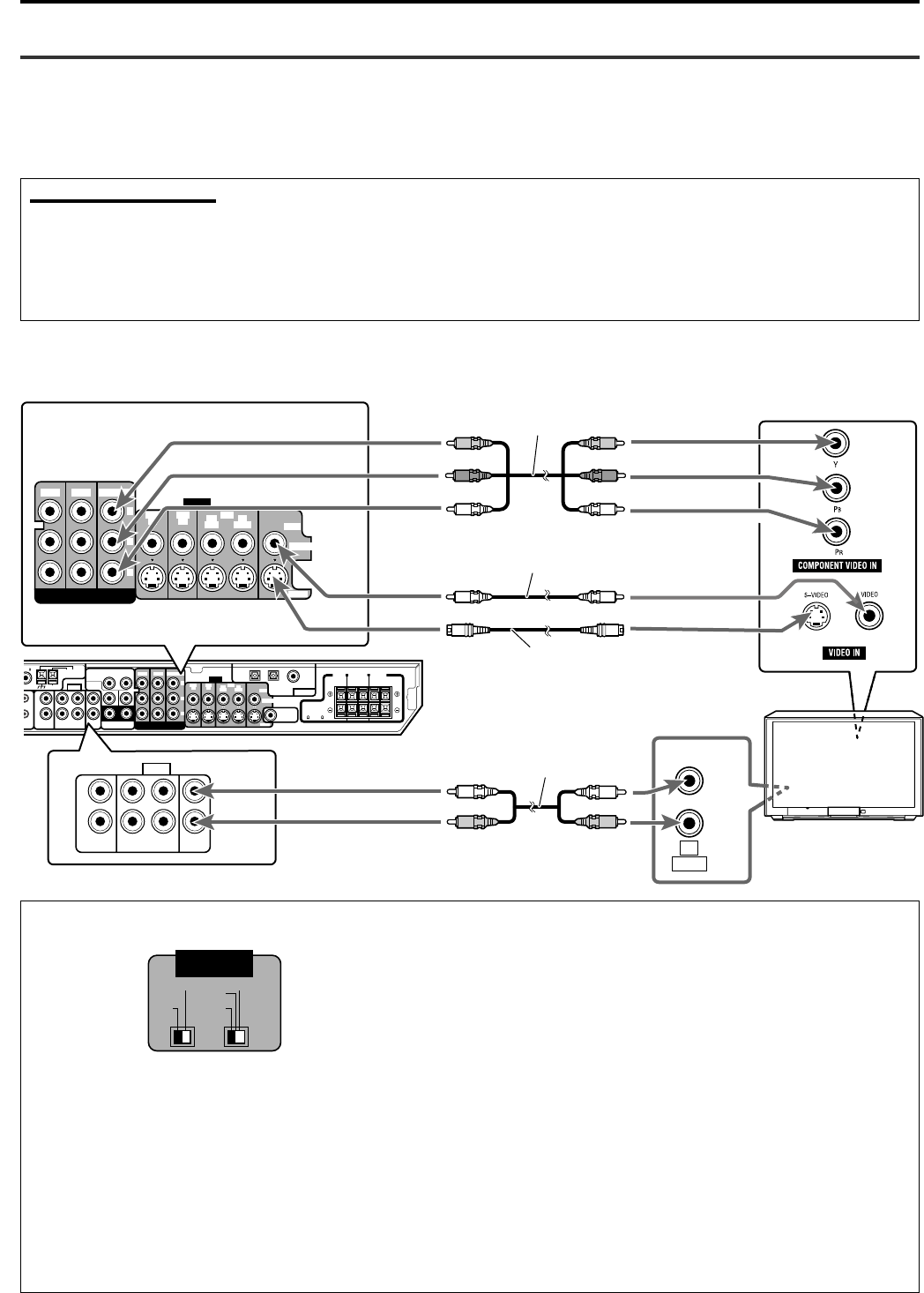
TV connection
DO NOT use a TV through a VCR or a TV with a built-in VCR; Otherwise, the picture may be distorted.
Connect using one of the video terminals.
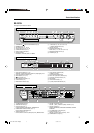
About VIDEO SIGNAL SELECTOR on XV-NK58SL
Component video cord (not supplied)
Composite video cord (not supplied)
S-video cord (not supplied)
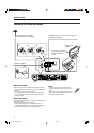
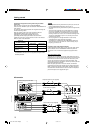
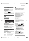
Connecting other video components
Turn off all components before making connections.
• Illustrations of the input/output terminals are typical examples. When you connect other components, refer also to their manuals since the
terminal names actually printed on the rear vary among different components.
Notes for video connection:
• You can use composite video cord or S-video cord for connecting the VCR to this receiver.
• You can use component video cord in addition to composite video cord and S-video cord for connecting your DVD player, TV and DBS tuner
to this receiver.
• By using S-video cord or component video cord, you can get a better picture quality—in the order: composite < S-video < component.
• To view the picture from the DVD player, DBS tuner or VCR on your TV, connect your TV to this receiver using the same type of cord for
connecting the DVD player, DBS tuner or VCR to this receiver.
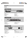
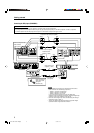
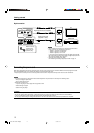
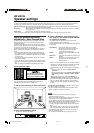
Selecting the 525i/525p/REMOTE selector position
You must change the 525i/525p/REMOTE selector position while
the player power is off. Otherwise, the changed setting is not
effective.
• If your television equipped with component jacks does not support
the progressive scanning mode, set the selector to “525i.”
• If your television equipped with component jacks supports the
progressive scanning mode, set the selector to “525p.”
• If you want to select the scanning mode between the interlace and
progressive modes (depending on the source condition, or when
connecting more than one television, etc.), set the selector to
“REMOTE.”
Selecting PAL or NTSC
Set the PAL/NTSC selector on the rear panel to “PAL” or “NTSC” to
match the color system of your TV. Make sure that the color system
of a DVD VIDEO/SVCD/video CD disc labeled on the package
matches your TV.
If you use a multi-color system TV, you can play discs recorded on
both PAL and NTSC systems by setting the PAL/NTSC selector
appropriately.
• Change the PAL/NTSC selector position in stop mode or with no
disc inserted. The changed setting is not effective if you change
the selector position in playback mode.
CONTINUED ON THE NEXT PAGE
Stereo audio cord (not supplied)
Red
Blue
Green
Red
Blue
Green
VIDEO SIGNAL
SELECTOR
NTSC REMOTE
PAL 525i
525
p
EN09-12RX-ES1&XV-NK58[A]f 03.6.6, 11:549