


2
Parts Identification
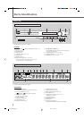
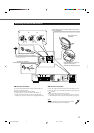
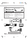
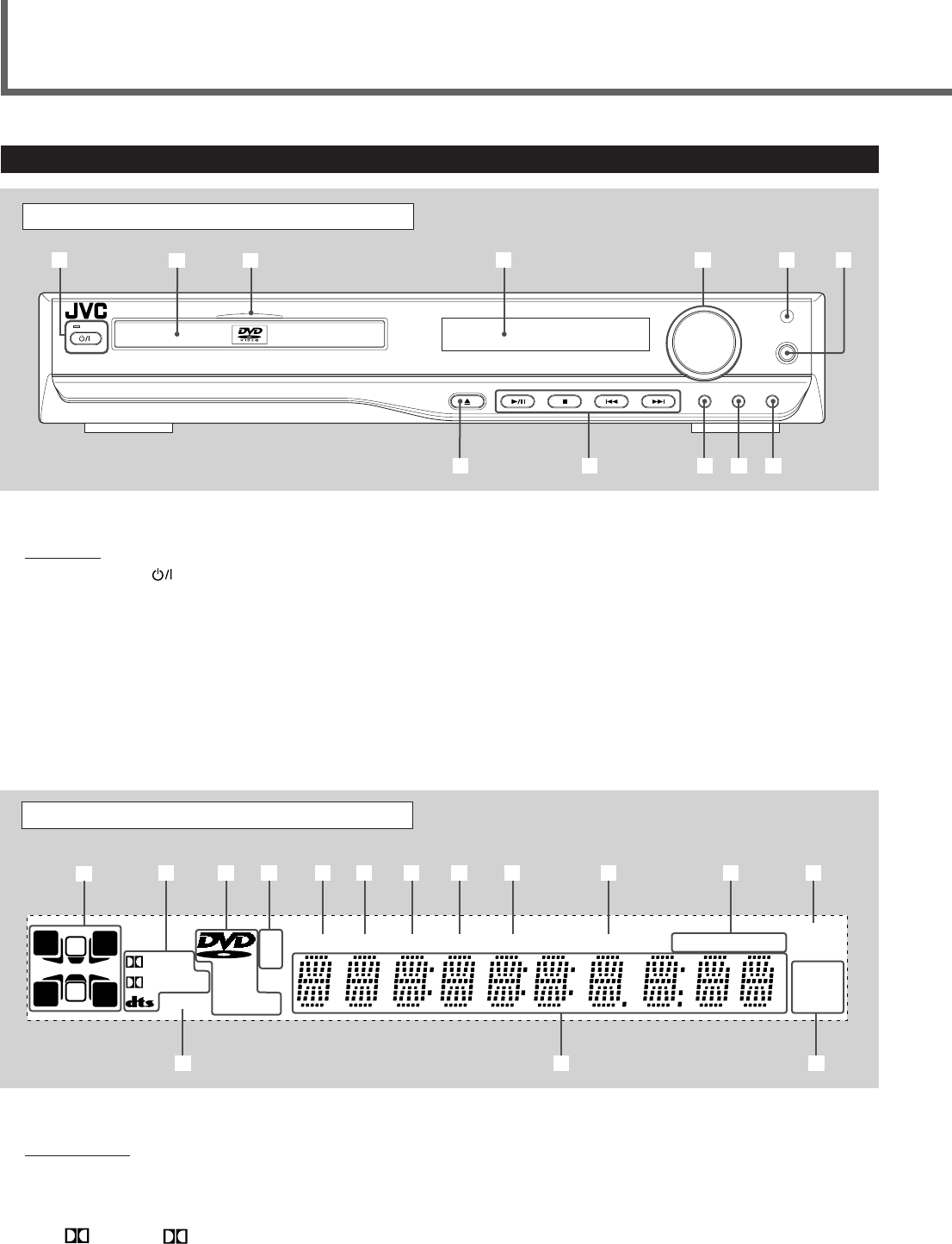
Front Panel
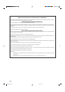
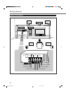
See pages in the parentheses for details.
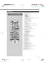
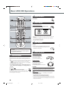
Display Window
1 Audio channel indicators
• Indicates audio channels currently source signal.
2 Sound signal indicators (19, 20)
• DIGITAL, PRO LOGIC II, and DTS
3 Disc indicators (23)
• DVD, CD, VCD, and MP3
4 Playback indicators
• 3 (play) and 8 (pause)
5 TITLE indicator (23)
6 TRK (track) indicator (23)
VOLUME
PHONES
DSPSURROUNDSOURCE
STANDBY
STANDBY/ON
DVD DIGITAL CINEMA SYSTEM TH-A35
1
2
8
9 p q w
3
45
67
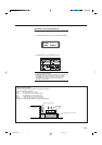
See pages in the parentheses for details.
Front Panel
1 STANDBY/ON button and STANDBY lamp (10 – 15)
2 Disc tray (10, 12)
3 Illumination lamp
4 Display window
5 VOLUME control (10, 12, 14)
6 Remote sensor
7 PHONES jack (17)
8 0 (open/close) button (10 – 13, 23, 39)
• Pressing this button also turns on the power and
changes the source to the DVD player.
9 3/8, 7, 4, and ¢ buttons
• Pressing 3/
8
also turns on the power and changes the
source to the DVD player.
p SOURCE button (10, 12, 14, 16, 46)
q SURROUND button (11, 13, 15, 17, 20)
w DSP button (11, 13, 15, 17, 20)
7 TUNED indicator (14, 46)
8 CHP (chapter) indicator (23)
9 PROG (program) indicator (29, 36)
p RDS indicator (48)
q Repeat mode indicators (27, 28, 34, 35)
• REPEAT, 1, and A–B
w Sleep indicator (18)
e STEREO indicator (47)
r Main display
t Frequency unit indicators
• MHz (for FM station) and kHz (for AM station)
Display Window
Center Unit
REPEAT 1
MHz
k
Hz
A–BRDSPROGCHPTUNEDTRKTITLE
CD
ProLogic II
DIGITAL
VCDSTEREO MP3
8
3
RS
R
L
LS
S
C
3
1
e r t
5432 6 7 8 9 p q w
EN01-09TH-A35[B].pm6 03.1.20, 11:25 AM2