


Chapter 7 • Pointing the antenna
60
1037312-0001 Revision A
Adjustment locations on the
antenna
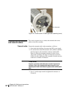
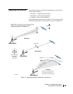
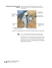
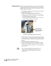
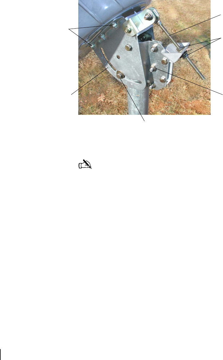
Figure 48 shows the mechanical adjustments for azimuth,
elevation, and polarization. All pointing adjustments require a
½-inch wrench.
Detailed procedures for adjusting the antenna are included in the
sections that follow. As you make pointing adjustments, tighten
the lockdown nuts or bolts enough to prevent movement of the
antenna reflector. When you are done pointing, you fully tighten
all lockdown nuts and bolts.
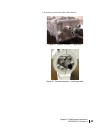
Figure 48: Pointing adjustments on the antenna—elevation, polarization, and azimuth
Note: The elevation lockdown hardware shown in Figure 48 may
be two nuts or two bolts (one on each side of the Az/El assembly).
Canister nuts (3).
Loosen to adjust
azimuth.
Polarization
lockdown
nuts (4)
Elevation
scale
Elevation lockdown bolts (2)
(coarse elevation adjustment)
(The polarization scale is shown
in Figure 51 on page 63.)
Fine elevation
adjustment nuts
Fine elevation
adjustment rod