


Chapter 4 • Installing a J-type radio assembly
38
1037312-0001 Revision A
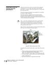
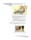
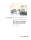
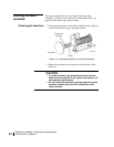
3. Place the neck of the feed horn into the upper mounting
bracket, and position the square end of the waveguide
transition close to the TRIA. See
Figure 30.
Make sure the feed horn packing material is out of the way so
it will not get stuck between the feed horn neck and the upper
mounting bracket.
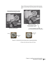
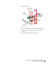
4. Attach the square end of the waveguide transition to the
TRIA using the provided M4 × 12-mm socket-head cap
screws and M4 lock washers with teeth on the inner edges.
(See
Figure 30.)
Insert the screws in the direction indicated by the white
arrows in
Figure 30.
Make sure the O-ring remains in the O-ring groove.
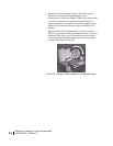
5. Use a long-shaft 3-mm ball driver to tighten the M4 cap
screws.
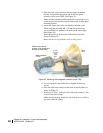
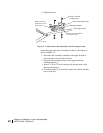
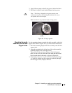
6. Place the feed horn clamp over the neck of the feed horn, as
shown in
Figure 31.
7. Insert two ¼-20 × 1-inch hex bolts (with lock washers)—one
on each side of the clamp.
Make sure the packing material is out of the way so it will not
get stuck under the clamp.
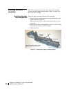
Figure 30: Attaching the waveguide transition to the TRIA
White arrows indicate
location of cap screws and
direction to insert them.
A fourth
cap screw
is not
visible
here.
Radio assembly
(TRIA)
Feed
horn