


Chapter 4 • Installing a J-type radio assembly
1037312-0001 Revision A
33
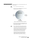
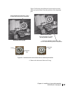
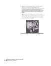
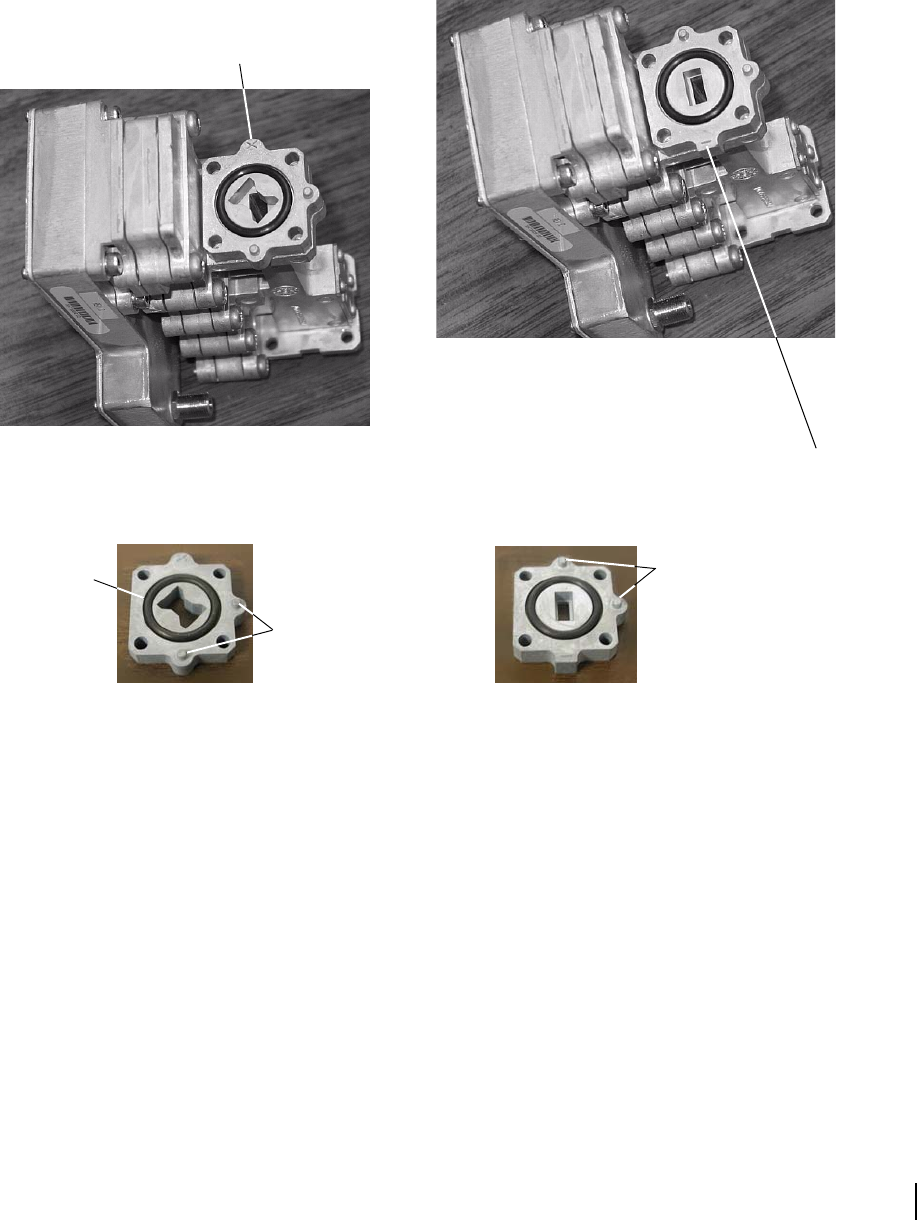
Figure 24 illustrates the difference between the horizontal
shim and vertical shim. Note the positions of the alignment
pins.
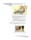
4. Remove the horizontal shim and O-ring.
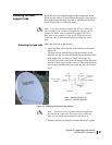
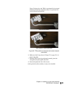
Figure 24: Horizontal shim and vertical shim for transmit polarization
TRIA
Horizontal shim in place
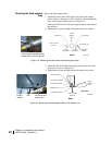
Vertical shim in place
(In this photograph, the TRIA
has not yet been rotated.)
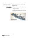
Alignment
pins
O-ring
Horizontal shim
Vertical shim
Alignment
pins
X here identifies horizontal shim. This X
is visible when the parts are assembled.
“ – ” mark here identifies vertical shim. This
mark is visible when the parts are assembled.