


Chapter 6 • Cabling and connections
1037312-0001 Revision A
51
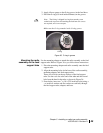
3. Coil the extra cable, leave a drip loop, and secure the transmit
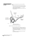
cable with cable ties.
4. Route the receive cable (marked with red electrical tape) over
the Az/El mount assembly, behind the reflector, and along the
feed support tube to the TRIA, in a configuration similar to
that shown in
Figure 38.
Do not exceed the minimum cable bending radius.
5. For the receive cable, leave a 138-inch service loop (11.5 ft),
secured to the mast, Az/El mount assembly, or reflector
bracket. This allows 10
ft for a service loop plus 18 inches for
installation of a future Ka-band radio upgrade.
6. Coil the extra cable, leave a drip loop, and secure the receive
cable with cable ties.
Ground connection
Ground the transmitter and mast. For specific grounding
procedures, refer to the sources listed in
Grounding on page 4.
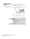
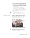
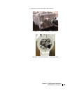
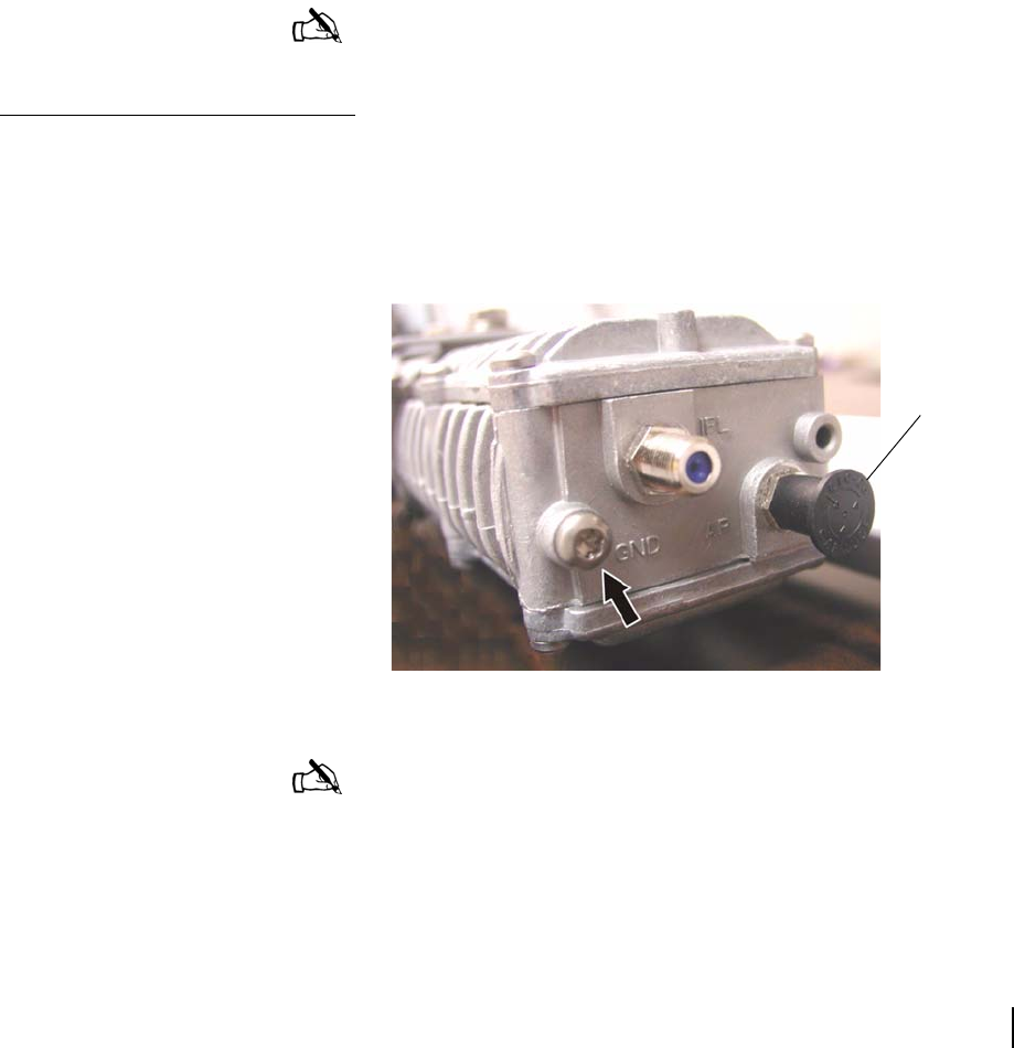
Figure 39 shows the location of the ground screw on the J-type
radio assembly. Figure 40 shows the ground screw on the
cradle-type radio assembly.
Note: When you connect the cables, tighten all radio and
ground block connectors with a torque wrench to 20
inch-lb.
Figure 39: Ground screw on J-type radio assembly (arrow)
(Not used)
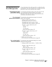
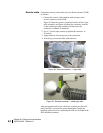
Note: The transmitter may look a little different than the one
shown in
Figure 40, but the connectors are still on the end of the
transmitter, as shown, and they are clearly marked: GND – ground.
IFL – interfacility link, for transmit cable.