


Chapter 3 • Assembling the antenna
26
1037312-0001 Revision A
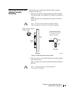
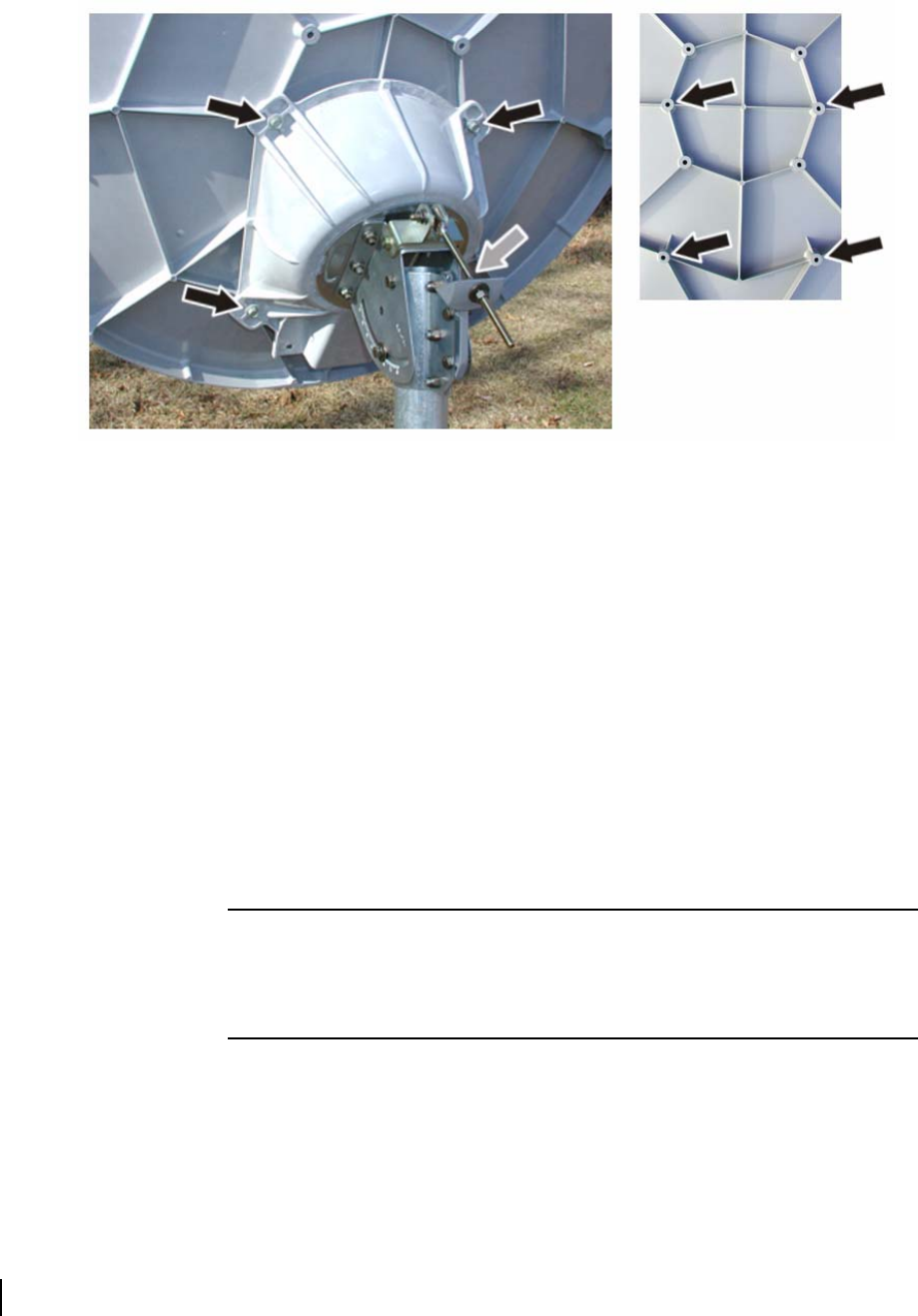
3. Insert two ¼-20 × 1-
3
⁄8-inch hex thread-cutting screws
(without washers) through the upper holes on the reflector
bracket and into the reflector holes indicated in
Figure 17
(upper arrows on the right photo).
4. Partially tighten the screws.
5. Insert two ¼-20 × 1-
1
⁄16-inch hex thread-cutting screws
(without washers) through the lower holes on the reflector
bracket and into the lower reflector holes.
6. Tighten each screw a little; then move on to the next screw.
7. Use a torque wrench to tighten the screws to 10 ft-lb force
maximum.
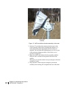
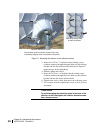
Figure 17: Mounting the reflector on the reflector bracket
Mounting holes (arrows)
on back of reflector
Reflector attached to bracket
Arrows above point to mounting screws. One screw,
indicated by the gray arrow, is not visible in this photo.
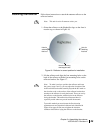
CAUTION
To avoid damaging the mounting holes in the back of the
reflector, do not overtighten the reflector bracket screws.
Use a torque wrench.