


Chapter 3 • Installing the radio and antenna assemblies
22
1035567-0001 Revision A
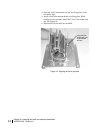
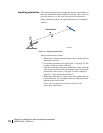
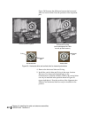
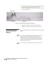
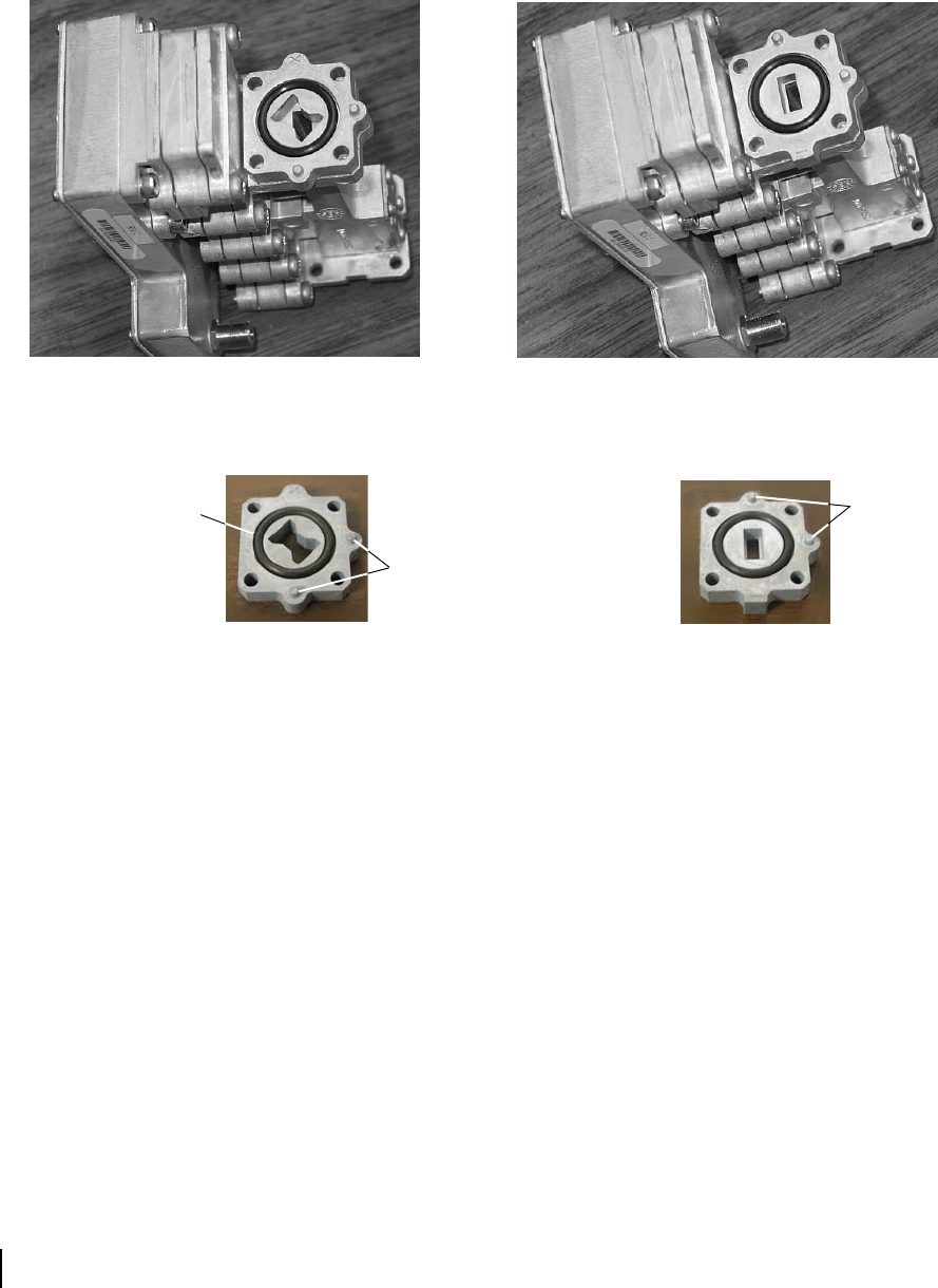
Figure 20 illustrates the difference between the horizontal
shim and vertical shim. Note the positions of the alignment
pins.
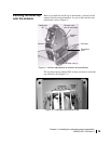
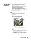
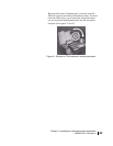
4. Remove the horizontal shim and O-ring.
5. Install the vertical shim and O-ring in the same location.
Because of its shape and alignment pins on the
transmit/receive isolation assembly (TRIA), the vertical shim
can only be installed in the position shown in
Figure 20
(upper right photo). Note the position of the alignment pins.
Likewise, the horizontal shim can only be installed in one
position.
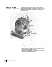
Figure 20: Horizontal shim and vertical shim for transmit polarization
TRIA
Horizontal shim in place
Vertical shim in place
(In this photograph, the TRIA
has not yet been rotated.)
Alignment
pins
O-ring
Horizontal shim
Vertical shim
Alignment
pins