


16 INSTALLATION AND CONNECTIONS
Installation and Connections
Video Connection Note:
• Composite and S-Video signals may only be
viewed in their native formats. S-Video inputs
may only be viewed when the AVR 310 is
connected to a TV set or video display with
S-Video capability.
System and Power Connections
The AVR 310 is designed for flexible use with
multiroom systems, external control compo-
nents and power amplifiers.
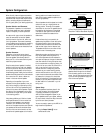
Main Room Remote Control Extension
If the receiver is placed behind a solid or
smoked glass cabinet door, the obstruction may
prevent the remote sensor from receiving com-
mands. In this event, an optional remote sensor
may be used. Connect the output of the remote
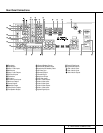
sensor to the
Remote IR Input jack a.
If other components are also prevented from
receiving remote commands, only one sensor is
needed. Simply use this unit’s sensor or a
remote eye by running a connection from the
Remote IR Output jack · to the Remote
IR Input jack on Harman Kardon or other com-
patible equipment.
Multiroom IR Link
The remote room IR receiver should be connected
to the AVR 310 via standard coaxial cable. Plug
the IR connection cable into the
Multiroom IR
Input
jack b on the AVR 310’s rear panel.
If other Harman Kardon compatible source
equipment is part of the main room installation,
the
Remote IR Output jack · on the rear
panel should be connected to the IR IN jack on
source equipment. This will enable the remote
room location to control source equipment
functions.
NOTE: All remotely controlled components
must be linked together in a daisy chain.
Connect the
IR OUT jack of one unit to the
IR IN of the next to establish this chain.
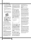
Multiroom Audio Connections
Depending on the distance from the AVR 310
to the remote room, two options are available
for audio connection:
Option 1: Use high-quality, shielded audio
interconnect cable from the AVR 310’s location
to the remote room. At the remote room, con-
nect the interconnect cable to a stereo power
amplifier.The amplifier will be connected to the
room’s speakers. No volume control is required,
as the AVR 310 and the remote IR link will pro-
vide that function. At the AVR 310, plug the
audio interconnect cables into the
Multi-
Room Output
jacks ‚ on the AVR 310’s
rear panel.
NOTE: The remote power amplifier must have
signal-sensing capability or be left on constantly to
assure automatic operation at the remote room.
Option 2: Place the amplifier that will provide
power to the remote location speakers in the
same room as the AVR 310, and connect the
Multiroom Output jacks ‚ on the rear
panel of the AVR 310 to the audio input of the
remote room amplifier. Use the appropriate
speaker wire to connect the optional power
amplifier to the remote speakers. High-quality
wire of at least AWG14 is recommended for
long multiroom connections.
IMPORTANT NOTE: Any cables run inside walls
should be CL3/FT4 rated, or carry any other certi-
fication that is required by the NEC or state and
local building and electrical codes.To avoid inter-
ference, audio and speaker cables should not be
parallel to, or run in the same conduits or path
with, AC cables. If you have any questions about
multiroom wiring, consult your dealer, custom
installer or low-voltage electrical contractor.
External Audio Power Amplifier
Connections
If desired, the AVR 310 may be connected to
optional, external audio power amplifiers.
When an external amplifier is used, connect the
Preamp Output jacks ⁄ to the inputs on the
external amplifier. Note that when external
amplifiers are used, the volume control is still
controlled by the AVR 310, although additional
volume controls on the external device may
impact the volume settings and output levels
from the AVR 310.
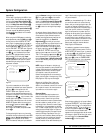
External Audio Decoder Connection
To provide for ultimate flexibility, the AVR 310
may be used in conjunction with optional,
external decoders for digital audio systems
other than the AVR 310’s own built-in Dolby
Digital and DTS decoding system or with DVD
players using the DVD Audio Format. If an
external decoder is used, connect the output
jacks of the decoder to the
6-Channel Direct
inputs ª, making sure to match channels.
These jacks may also be used for connections to
devices such as DVD players or High Definition
Television (HDTV) sets or decoders that feature
built-in digital surround decoders. Although the
digital decoding system in the AVR 310 will typi-
cally provide audio performance that is superior
to other decoders, you may use these jacks to
provide an additional 6-channel input for connec-
tion to a DVD player or HDTV set with a built-in
decoder and discrete 6-channel analog outputs.
AC Power Connections
This unit is equipped with two accessory AC
outlets. They may be used to power accessory
devices, but they should not be used with high-
current draw equipment such as power ampli-
fiers. The total power draw to each outlet may
not exceed 100 watts.
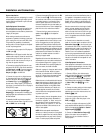
The
Switched AC Accessory fl outlet will
receive power only when the unit is on. This is
recommended for devices that have no power
switch or a mechanical power switch that may
be left in the “ON” position.
NOTE: Many audio and video products go into
a Standby mode when they are used with
switched outlets, and cannot be fully turned on
using the outlet alone without a remote control
command.
The
Unswitched AC Accessory ‡ outlet will
receive power as long as the unit is plugged
into a powered AC outlet.
Finally, when all connections are complete, plug
the power cord into a nonswitched 110-volt AC
wall outlet.You’re almost ready to enjoy the
AVR 310!