


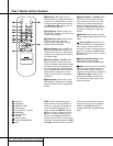
10 REAR PANEL CONNECTIONS
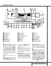
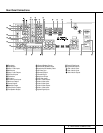
Rear Panel Connections
¡ Tape Inputs: Connect these jacks to the
PLAY/OUT jacks of an audio recorder.
™ Tape Outputs: Connect these jacks to the
RECORD/INPUT jacks of an audio recorder.
£ Video 1 Audio Inputs: Connect these
jacks to the
PLAY/OUT audio jacks on a VCR
or other video source.
¢ AM Antenna: Connect the AM loop antenna
supplied with the receiver to these terminals. If an
external AM antenna is used, make connections
to the
AM and GND terminals in accordance
with the instructions supplied with the antenna.
∞ Video 1 Audio Outputs: Connect these
jacks to the
RECORD/INPUT audio jacks on
a VCR.
§ DVD Audio Inputs: Connect these jacks
to the analog audio jacks on a DVD or other
video source.
¶ FM Antenna: Connect the supplied indoor or
an optional external FM antenna to this terminal.
• CD Inputs: Connect these jacks to the out-
put of a compact disc player or CD changer.
ª 6-Channel Direct Inputs: If an external
digital audio decoder is used, connect the out-
puts of that decoder to these jacks.
‚ Multiroom Outputs: Connect these jacks
to an optional audio power amplifier to listen
to the source selected by the mulitroom system
in a remote room.
⁄ Preamp Outputs: These jacks may be
connected to an external power amplifier.
¤ Subwoofer Output: Connect this jack to
the line-level input of a powered subwoofer. If
an external subwoofer amplifier is used, con-
nect this jack to the subwoofer amplifier input.
‹ Video Monitor Outputs: Connect this
jack to the composite or S-Video input of a TV
monitor or video projector to view the on-screen
menus and the output of any standard video
source selected by the receiver’s video switcher.
› Front Speaker Outputs: Connect these
outputs to the matching + or – terminals on
your front speakers.When making speaker
connections, always make certain to maintain
correct polarity by connecting the red (+) termi-
nals on the AVR 310 to the red (+) terminals on
the speaker and the black (–) terminals on the
AVR 310 to the black (–) terminals on the
speakers. (See page 15 for more information on
speaker polarity.)
fi Surround Speaker Outputs: Connect
these outputs to the matching + or – terminals
on your left and right surround speakers.When
making speaker connections always make cer-
tain to maintain correct polarity by connecting
the red (+) terminals on the AVR 310 to the red
(+) terminals on the speakers and the black (–)
terminals on the AVR 310 to the black (–) ter-
minals on the speakers. See page 15 for more
information on speaker polarity.
fl Switched AC Accessory Outlet: This
outlet may be used to power any device you
wish to have turned on when the AVR 310 is
turned on with the
System Power Control
switch 2.
‡ Unswitched AC Accessory Outlet: This
outlet may be used to power any AC device.
The power will remain on at this outlet regard-
less of whether the AVR 310 is on or off.
Note: The total power consumption of all
devices connected to the accessory outlets
should not exceed 100 watts.
° AC Power Cord: Connect the AC plug to
an unswitched AC wall output.
· Remote IR Output: This connection per-
mits the IR sensor in the receiver to serve other
remote controlled devices. Connect this jack to
the “IR IN” jack on Harman Kardon (or other
compatible) equipment.
a Remote IR Input: If the AVR 310’s front-
panel IR sensor is blocked due to cabinet
doors or other obstructions, an external IR
sensor may be used. Connect the output of
the sensor to this jack.
b Multiroom IR Input: Connect the output of
an IR sensor in a remote room to this jack to
operate the AVR 310’s multiroom control system.
c DVD Video Inputs: Connect these jacks to
the composite or S-Video output jacks on a
DVD or other video source.
d Video 1 Video Outputs: Connect these
jacks to the
RECORD/INPUT composite or
S-Video jack on a VCR.
e Video 3 Video Inputs: Connect these
jacks to the
PLAY/OUT composite or S-Video
jacks on a VCR or other video source.
f Video 2 Video Inputs: Connect these
jacks to the
PLAY/OUT composite or S-Video
jacks on a VCR or other video source.
g Video 2 Video Outputs: Connect these
jacks to the
RECORD/INPUT composite or
S-Video jacks on a VCR.
h Video 1 Video Inputs: Connect these
jacks to the
PLAY/OUT composite or S-Video
jacks on a VCR or other video source.
i Optical Digital Inputs: Connect the opti-
cal digital output from a DVD player, HDTV
receiver, LD player or CD player to these jacks.
The signal may be either a Dolby Digital signal,
a DTS signal or a standard PCM digital source.
j Coaxial Digital Inputs: Connect the coax
digital output from a DVD player, HDTV receiver,
LD player or CD player to these jacks. The signal
may be either a Dolby Digital signal, DTS signal
or a standard PCM digital source. Do not con-
nect the RF digital output of an LD player to
these jacks.
k Digital Audio Outputs: Connect these
jacks to the matching digital input connector
on a digital recorder such as a CD-R or
MiniDisc recorder.
Video 3 Audio Inputs: Connect these
jacks to the
PLAY/OUT audio jacks on a VCR
or other video source.
Video 2 Audio Inputs: Connect these
jacks to the
PLAY/OUT audio jacks on a VCR
or other video source.
Video 2 Audio Outputs: Connect these
jacks to the
RECORD/INPUT audio jacks on a
VCR or other video source.
33
32
31