23
The AVR 147 is Simplay HD-verified for compatibility via the HDMI
connection with other Simplay HD-verified products.
If your source or video display is equipped with a DVI (Digital Video
Interface) input, you may use an HDMI-to-DVI adapter (not included).
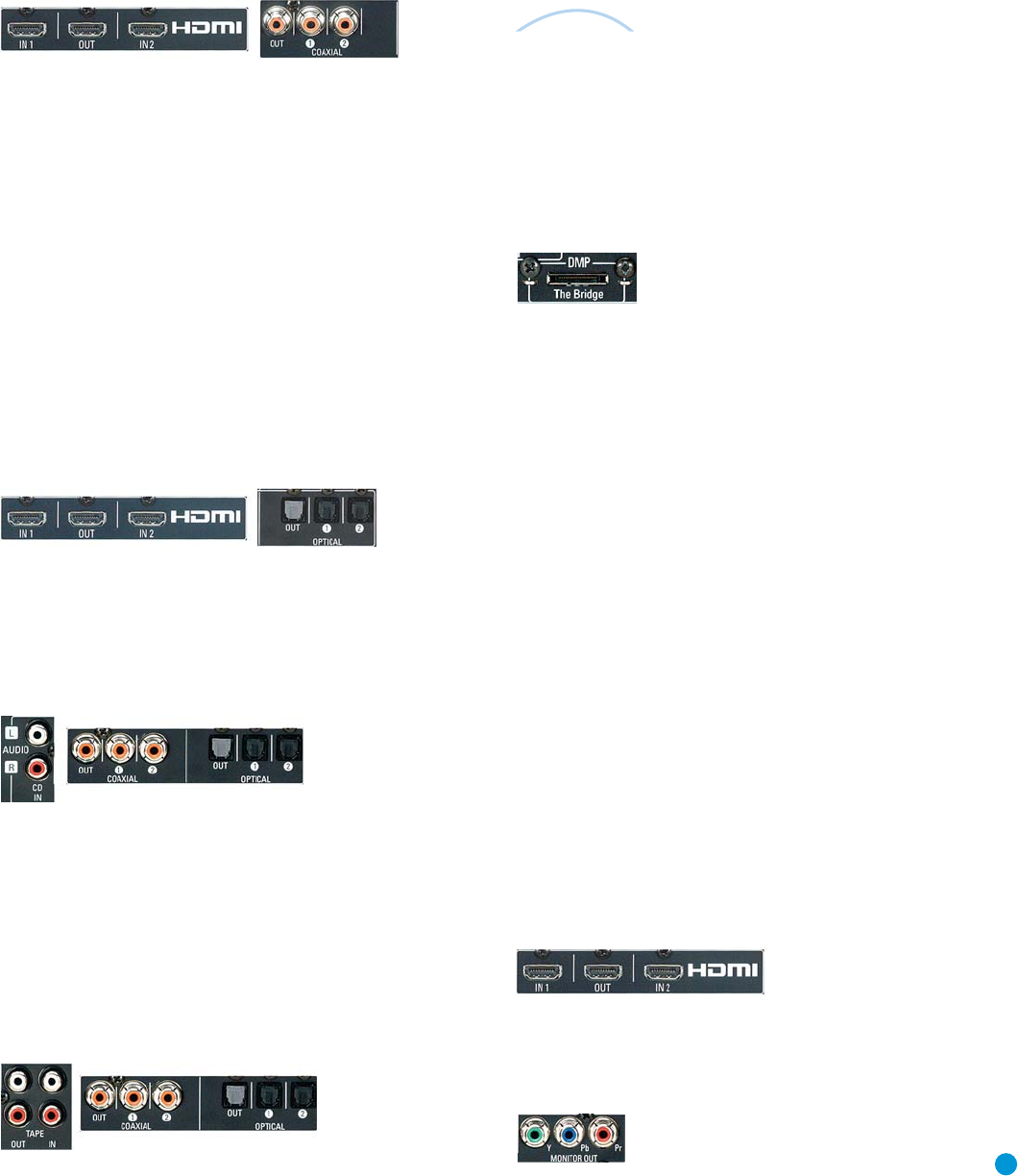
Figure 24 – HDMI 1 and Coaxial 2 Inputs
HDMI 2 Source
The HDMI 2 source is used with a second device that is capable of
outputting digital video through an HDMI connection, such as a DVD,
HD-DVD or Blu-ray Disc player. The HDMI 2 source is not used with
any of the 2-channel analog audio or video inputs on the AVR 147.
Since the AVR 147 is not capable of processing either the audio or video
signal transmitted via the HDMI connection, you will need to connect the
source’s optical digital audio output to the Optical 2 digital audio input
on the AVR 147, or use the 6-/8-channel inputs. See Figure 25. You will
also need to make sure your video display is HDMI-capable, and for many
source devices, the display must be HDCP-compliant (High-Bandwidth
Digital Content Protection) in order to display copy-protected materials.
If your source or video display is equipped with a DVI (Digital Video
Interface) input, you may use an HDMI-to-DVI adapter (not included).
Figure 25 – HDMI 2 and Optical 2 Inputs
CD
The CD source is used for a strictly audio device, such as a CD player.
Referring to Table 2, connect your CD player to the CD Analog Audio
inputs and to any available digital audio input. See Figure 26.
Figure 26 – CD Audio Inputs and Digital Audio Inputs
No video connections are needed.
Tape
The Tape source is used for audio-only recorders, such as a CDR,
MiniDisc or cassette deck.
Referring to Table 2, connect your recorder to the Tape Analog
Audio inputs and outputs, and to any available digital audio input
(and corresponding digital audio output). See Figure 27.
Figure 27 – Tape Audio Inputs and Outputs, and Digital Audio Inputs and Outputs
Remember to connect the
output
jacks on your recorder to the Tape
or digital audio
input
jacks on the AVR, and the
input
jacks on your
recorder to the Tape or digital audio
output
jacks on the AVR.
No video connections are needed.
With Harman Kardon’s optional The Bridge, you can enjoy audio, video
or still images stored on your iPod (not included), use your AVR 147
remote control to operate the iPod, and even charge the iPod while it’s
docked in The Bridge.
Simply plug the proprietary cable from The Bridge into the special
The Bridge/DMP connector on the rear of the AVR 147. See Figure 28.
Refer to the owner’s manual for The Bridge to select the appropriate
insert to match your iPod.
Figure 28 – The Bridge/DMP Connector
Step Five – Connect the Video Display
Only video connections should be made between the receiver and
your video display (TV), unless your TV is the source for your television
programming (see Video 3 Source above).
You will need to make a video connection for each type of video used
for your sources. In addition, even if you didn’t use S-video or composite
video for any of your sources, one of these video monitor connections
is required to view the AVR 147’s on-screen menus and displays.
First, determine what types of video your display is capable of handling.
Remember that HDMI is preferred, followed by component video, S-video
and then composite video. Ideally, this guided you in selecting the video
connections for your sources.
Next, note which types of video connections you used for your source
devices. Make sure you didn’t use a better type of video connection
for a source than your video display can handle. If so, you will need to
disconnect the source and use a video connection that’s compatible
with your display.
If you used an HDMI video connection for any of your sources, then
connect the HDMI Output on the AVR to an HDMI input on your video
display. See Figure 29. As mentioned previously, you will need to make
a separate digital audio connection from each source device to the
AVR 147, and you will also need to consult the owner’s guide for your
television to learn the proper procedure for disabling or muting the audio.
Figure 29 – HDMI Output
If you used component video for any sources, connect the Component
Video Monitor outputs on the receiver to one set of component video
inputs on your display. See Figure 30. Make a note of how these inputs
are labeled on the display.
Figure 30 – Component Video Monitor Outputs
The
Bridge
TM
INSTALLATION
AVR147-OM.qxd 2/6/07 3:17 PM Page 23


