


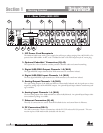
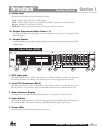

9. Zone Control Inputs 1-12 (RJ-45)
These RJ-45 connections are used to receive control information from up to 12 ZC wall panel control-
lers.
10. Word Clock BNC Connection
This connection allows the DriveRack 4800 or 4820 to lock to a master system clock. It is not termi-
nated. For best results we recommend using “T” connectors when setting up a BNC Word Clock net-
work and terminating the end of of this network with a 75 ohm BNC terminator. (See Appendix 6).
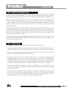
11. Pin Lift Switch
Analog Inputs 1&2, and 3&4 of the DriveRack 4800/4820 share a Ground Lift Switch (Pin 1 lift).
System ground loops can cause hum; this hum can be reduced by pressing the Ground Lift Switch.
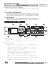
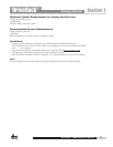
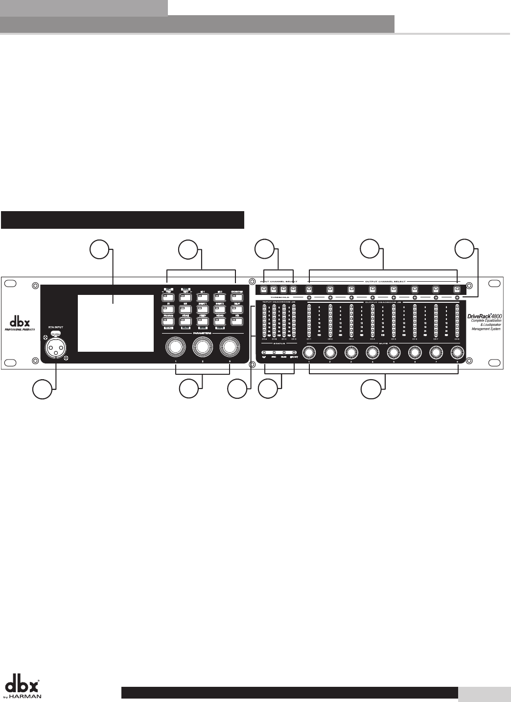
1.2 - Front Panel (4800)
1
2
3
4
5
6
7
8
9
10
1. LCD Display
The color 1/4 VGA (320x240) display provides viewing of all parameters and attributes of the
DriveRack 4800.
2. Function Buttons
The Function buttons of the DriveRack 4800 allow direct access to all editing and navigating functions
of the DriveRack 4800. The functions of the aforementioned buttons are as follows:
PREV is used to navigate back through the various pages of any module. Pressing and
holding the PREV button allows you to enter Copy/Paste Mode, where subsequent presses
of PREV allow copying all the function DSP parameters.
NEXT is used to navigate forward through the various pages of any module. Pressing
and holding the NEXT button allows you to enter Copy/Paste Mode, where subsequent
presses of NEXT allow pasting of all the function DSP parameters.
EQ 1 is used to select and/or enter the first Input EQ module or the Output EQ module.
EQ 2 is used to select and/or enter the second Input EQ module or the Output EQ module.
BANDPASS is used to select and/or enter the Bandpass/Crossover function.
Getting Started
Section 1
3
DriveRack
®
4800/4820 User Manual
DriveRack
®