


vii
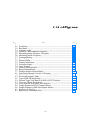
List of Figures
Figure Title Page
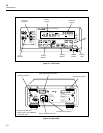
2-1. Front Panel ............................................................................................................. 2-2
2-2. Rear Panel .............................................................................................................. 2-2
2-3. Adjusting Handle.................................................................................................... 2-3
2-4. Summary of Basic Pushbutton Operations............................................................. 2-4
2-5. Measuring Voltage, Resistance, or Frequency....................................................... 2-7
2-6. Measuring Current or Frequency ........................................................................... 2-7
2-7. Continuity Testing.................................................................................................. 2-8
2-8. Diode Testing......................................................................................................... 2-8
3-1. Primary Display...................................................................................................... 3-2
3-2. Display Annunciators............................................................................................. 3-3
3-3. Secondary Display.................................................................................................. 3-3
3-4. Input Terminals ...................................................................................................... 3-4
3-5. Function Selection Buttons .................................................................................... 3-6
3-6. Range Selection Buttons ........................................................................................ 3-8
3-7. Function Modifier Selection Buttons ..................................................................... 3-11
4-1. Dual Display Showing Volts AC and Frequency................................................... 4-2
4-2. DC Voltage and DC Current Measurement on Input Signal.................................. 4-4
4-3. Waveform Comparison Chart ................................................................................ 4-11
5-1. Typical IEEE-488 Input Strings............................................................................. 5-10
5-2. External Trigger Using Receive Pin (RX) of RS-232 Interface............................. 5-13
5-3. Overview of Status Data Structures ....................................................................... 5-15
5-4. Event Status and Event Status Enable Registers.................................................... 5-16
5-5. Sample Program for RS-232 Computer Interface .................................................. 5-31
5-6. Sample Programs for IEEE-488 Computer Interface............................................. 5-32
6-1. Replacing the Line Fuse......................................................................................... 6-2
6-2. Replacing the 100mA Input Fuse........................................................................... 6-3