Fluke 433/434
Users Manual
11-2
e
ENTER
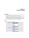
The table displays power data for each phase and in total: real or active power (kW),
apparent power (kVA, the product of rms voltage and current), reactive power (kVAR,
the reactive component of apparent power caused by phase shift between AC current and
voltage in inductors and capacitors), power factor (PF, the ratio of real power to apparent
power for the total rms including harmonics), displacement power factor (DPF or cos ϕ,
the ratio of real power to apparent power for fundamental), and the 12 or 10 cycle rms
values of current and voltage.
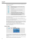
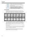
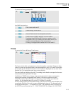
Symbols indicate if a load is capacitive (
) or inductive ( ).
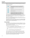
A popup table with energy usage by phase and in total can be activated on the Fluke 434
by pressing the F3 – ENERGY softkey. The table shows real energy (kWh), apparent
energy (kVAh), and reactive energy (kVARh) The energy measurement starts when
Power & Energy is started. The readout can be reset with function key F5.
By a using TIMED start of the measurement, the Fluke 434 can be used to measure
energy usage during a predefined period of time. TIMED start can be adjusted when
switching from HOLD to RUN with function key F5. Temporarily Close ENERGY to
make function key F5 available for HOLD/RUN operation.
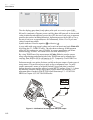
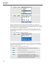
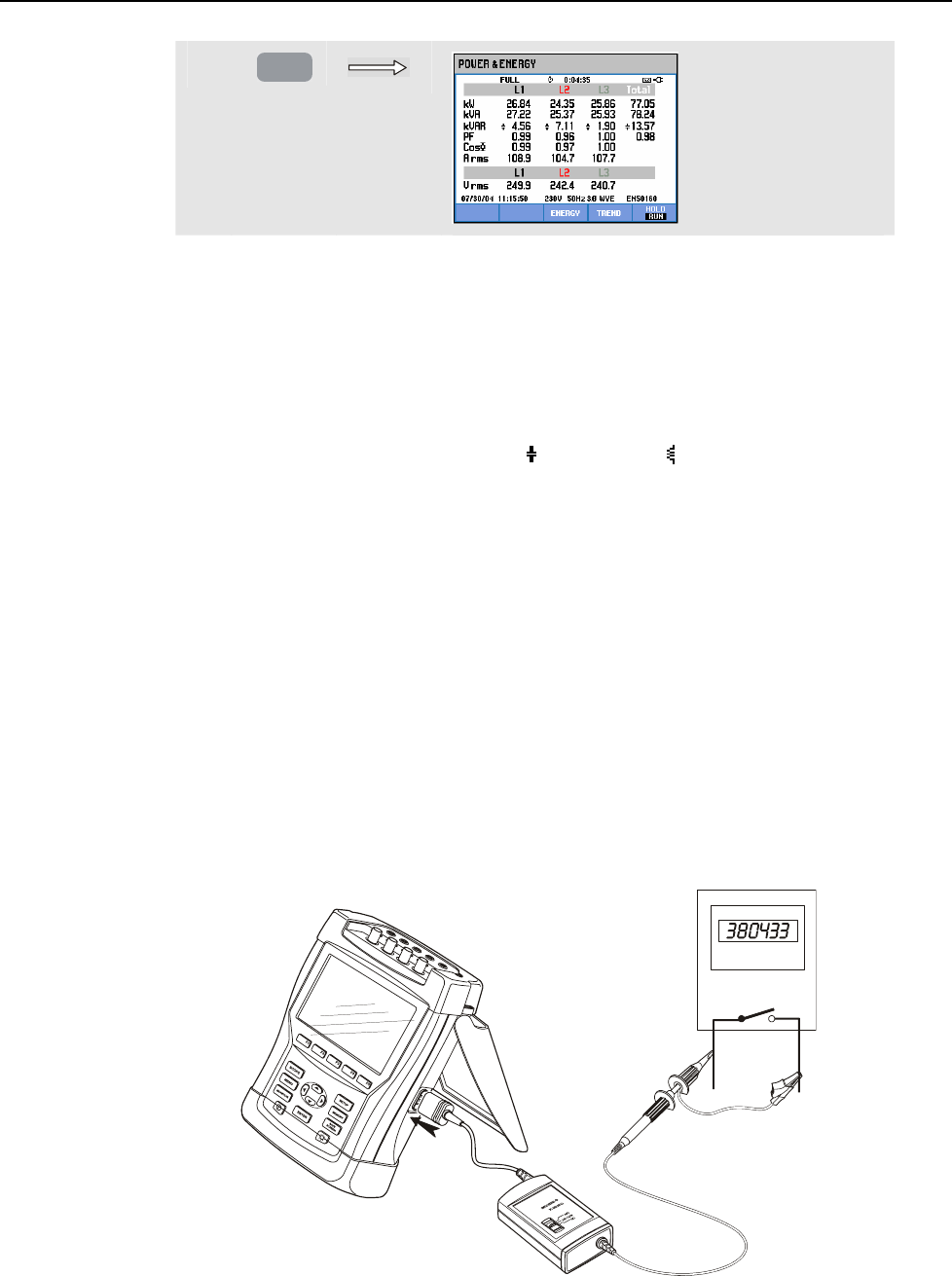
Pulse count mode counts pulses like those available at the pulse output of certain types of
energy meters. This can be used to as a quick test for revenue meter error. The pulse
output is measured by means of an Optical Isolated Trigger Probe that is connected
between the pulse output and the Analyzer’s optical RS-232 interface. Figure 11-1 shows
the measuring setup. The energy usage (kWh) per pulse must be set in advance. The
adjustment menu is reached via the SETUP key and function key F3 – FUNCTION
PREF. See Chapter 18, FUNCTION PREFerences.
Figure 11-1. Verification of an energy meter with pulse output


