


Fluke 433/434
Users Manual
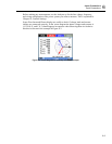
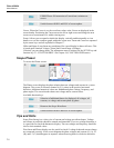
6-2
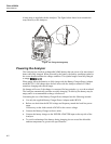
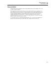
Figure 6-1. Mounting the decals for voltage and current inputs
De-energize power systems before making connections whenever possible. Avoid
working alone and work according to the warnings listed in Chapter 1, Safety
Information.
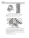
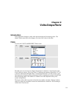
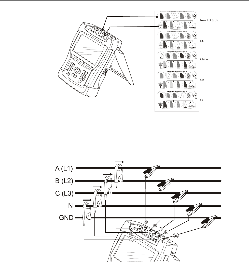
For a 3-phase system make the connections as shown in Figure 6-2.
Figure 6-2. Connection of Analyzer to 3-phase distribution system
First put the current clamps around the conductors of phase A (L1), B (L2), C (L3), and
N(eutral). The clamps are marked with an arrow indicating the correct signal polarity.
Next make the voltage connections: start with Ground and then in succession N, A (L1),
B (L2), and C (L3). For correct measuring results, always connect the Ground input.
Always double-check the connections. Make sure that current clamps are secured and
completely closed around the conductors.
For single phase measurements, use current input A (L1) and the voltage inputs Ground,
N(eutral), and phase A (L1).
A (L1) is the reference phase for all measurements.