


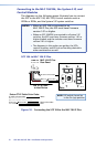
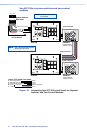
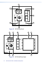
Two SCP 226s to system switcher and two control
modules
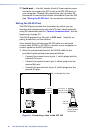
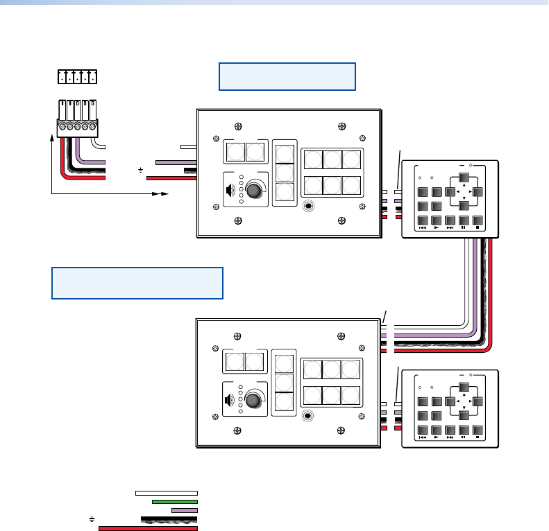
Figure 15. Connecting Two SCP 26 Control Panels to a System
Switcher and Two Control Modules
SCP 226
SCP 226
C
B
A
C
B
A
E
E
C
B
A
E
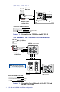
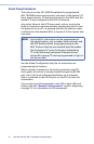
Extron CTLP Cable Color Code:
200' (61 m) max.
to Last Device
IRCM-DV+
Control Module
Address 1 and 2
IRCM-DV+
Control Module
Address 3 and 4
E
C
B
A
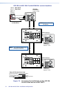
SCP Communication
IRCM, RCM
+12 VDC
Ground ( ) & Drain Wire
Ground ( ) & Drain Wire
E
D
C
B
A
SCP Communication
Modulated IR (for IR Link)
Control Module Communication
+12 VDC
= White
= Green
= Black & Drain Wire
= Violet
= Red
NOTE: Maximum Two SCPs
Per System
NOTE: DIP switch #4 must be
in the On (up) position.
VOLUME
SCP 226
IR
DISPLAY
Extron
1
2
3
4
5
6
ON
OFF
PIC
MUTE
AUTO
IMAGE
PC VCR
DVD
LAPTOP
DOC
CAM
G+V
CM IR
SCP
E
CBDA
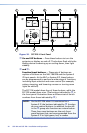
System Switcher
Rear Panel
VOLUME
SCP 226
IR
DISPLAY
Extron
1
2
3
4
5
6
ON
OFF
PIC
MUTE
AUTO
IMAGE
PC VCR
DVD
LAPTOP
DOC
CAM
DVD & VCR CONTROL
PLAYNEXT/FWDPAUSE STOP
TUNER
Tx
PREV/REW
ENTER
TITLE MENU
TV/VCR
DVD VCR
DVD & VCR CONTROL
PLAYNEXT/FWDPAUSE STOP
TUNER
Tx
PREV/REW
ENTER
TITLE MENU
TV/VCR
DVD VCR
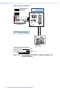
5-pole Connector
5-pole Connector
5-pole Connector
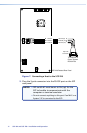
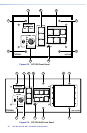
NOTE: Use a different DIP switch 2
setting for each SCP.
SCP 104 and SCP 226 • Installation and Operation
17