


Connecting to the MLC 104/226, the System 5 IP, and
Control Modules
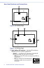
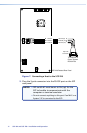
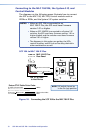
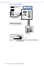
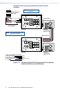
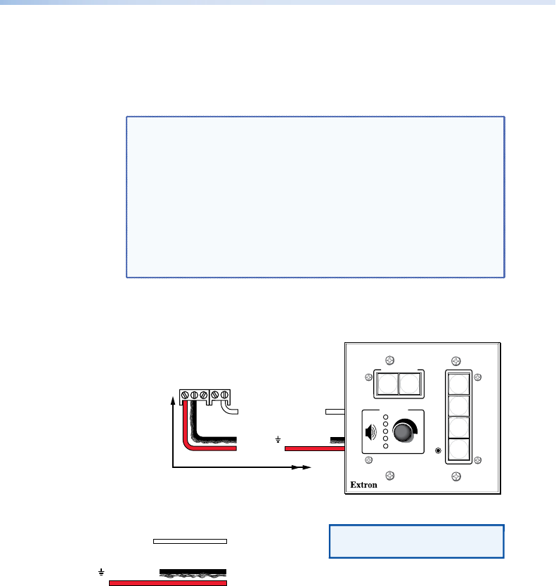
The diagrams on the following pages illustrate how to connect
the SCP to the MLC 104, MLC 226, control modules such as
IRCMs or RCMs, and the System 5 IP system switcher.
NOTES: • When an SCP 104 is connected to an
MLC 104 IP Plus, the SCP must have firmware
version 1.01 or higher.
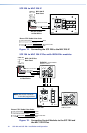
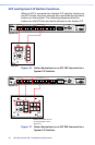
• When an SCP 104/226 is connected to a System 5 IP
switcher, the SCP must have firmware version 1.01 or
higher loaded, and the switcher must have firmware
version 2.01 or higher.
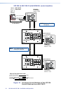
• The diagrams in this section are guides; the SCPs,
control modules, and IR Link can be daisy-chained in
other combinations as well.
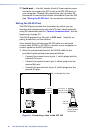
SCP 104 to MLC 104 IP Plus
SCP 104
200' (61 m) max.
to Last Device
E
B
A
SCP Communication
+12 VDC
Ground ( ) & Drain Wire
MLC 104 IP Plus
Rear Panel
Extron CTLP Cable Color Code:
Ground ( ) & Drain Wire
E
D
C
B
A
SCP Communication
Modulated IR (for IR Link)
Control Module Communication
+12 VDC
= White
= Black & Drain Wire
= Red
COMM LINK
A B C D E
+V OUT
GROUND
CM
IR IN
SCP
CONFIG
DISPLAY
VOLUME
SCP 104
ON
PC
VCR
DVD
OFF
1
2
3
4
NOTE: DIP switch 4 must be
in the On (up) position.
Figure 10. Connecting the SCP 104 to the MLC 104 IP Plus
SCP 104 and SCP 226 • Installation and Operation
13