Installing the Equipment
Warning!
The Technical Earth is not a Protective earth for electric shock protection.
This unit must be correctly earthed through the molded plug supplied. If the local
mains supply does not have an earth conductor do not connect the unit. Contact
Customer Services for advice.
Before connecting the unit to the supply, check the supply requirements in Annex B
of the Reference Guide.
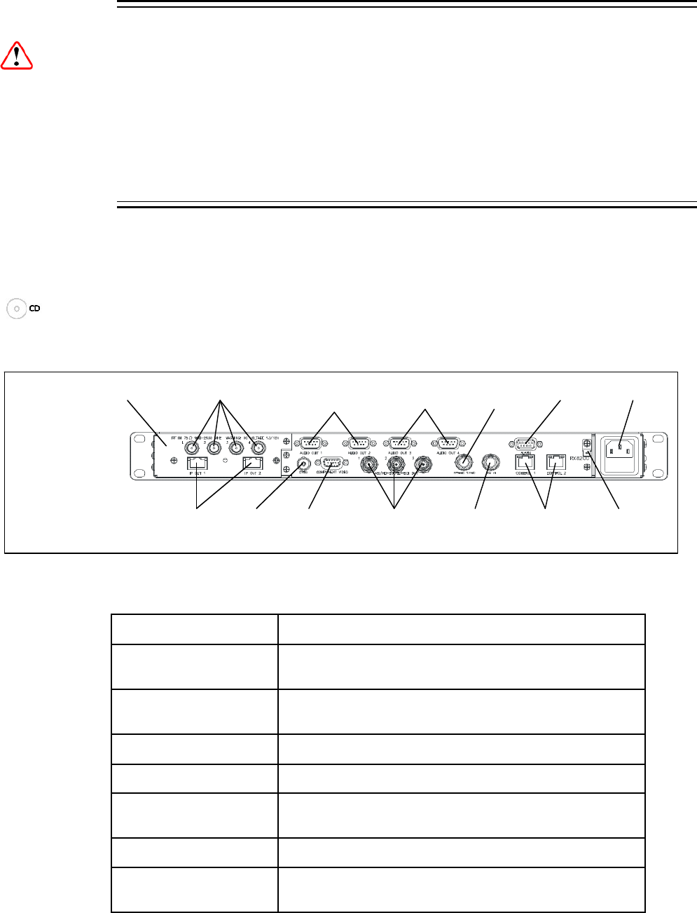
2.4 Rear Panel Connectors
Always use the specified cables supplied for signal integrity and compliance with
EMC requirements (see the Reference Guide).
Note: Rear panel connectors may differ, depending on the options selected.
ASI/HD-SDI/SD-
SDI OUT 1-3
TECHNICAL
EARTH
AC POWER
IP OUT 1-2
RF IN 1-4
CVBS
ALARM
CONTROL
1-2
A
SI INPUT
RX8200
Sample configuration
with: Satellite input,
frame sync, HD video
output, IP Transport
Stream output and 2x
Audio output modules
installed.
AUDIO OUT (1)
1-2
INPUT MODULE
AUDIO OUT (2)
3-4
COMPONENT
VIDEO
FRAME
SYNC
Figure 1 Rear Panel Connectors
Table 4 Types of Connector
Type of Connector Description
RF IN 1,2,3 & 4
F-type connectors for DVB or DVB-S2 modulated input
feed.
AUDIO OUT 1,2,3 & 4
9-way male D-type connectors for analogue and
balanced digital audio output.
FRAME SYNC
75 Ω BNC connector for frame synching input.
ALARM 9-way male D-type connector for alarm signal output.
IP OUT 1 & 2
8-way RJ-45 connectors for 1000BaseT IP output feed &
de-encapsulated IP data
CVBS
75 Ω BNC connector for SD composite video output.
COMPONENT VIDEO
9-way male D-type connectors for component video
output.
EN/LZT 790 0009 R1A 2011-03-30
10 (44)


