Installation Manual 29
I/O Wiring – Model 2400S PROFIBUS-DP and DeviceNet Transmitters
Power Supply I/O Wiring – DP and DNI/O Wiring – ANBefore You Begin Power Supply I/O Wiring – DP and DNI/O Wiring – ANBefore You Begin Power Supply I/O Wiring – DP and DNI/O Wiring – ANBefore You Begin Power Supply I/O Wiring – DP and DNI/O Wiring – ANBefore You Begin
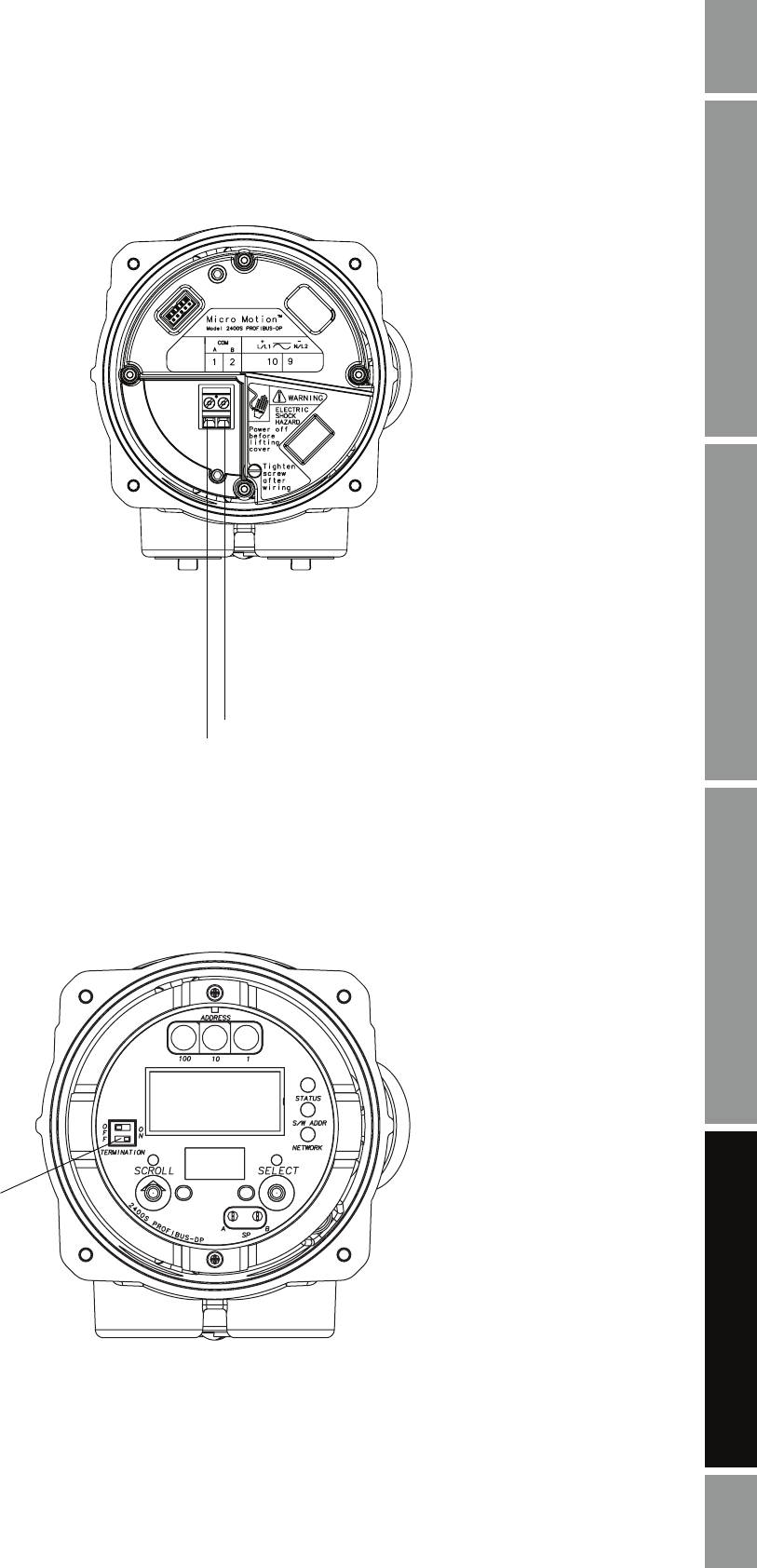
Figure 4-1 Model 2400S PROFIBUS-DP I/O wiring
4.3.1 Enabling internal termination
Model 2400S PROFIBUS-DP transmitters have a switch on the user interface module to enable
internal termination impedance. Refer to Figure 4-2.
Figure 4-2 Model 2400S PROFIBUS-DP internal termination impedance switch
Spur to PROFIBUS-DP segment according to the
Installation Guideline for PROFIBUS-DP/FMS
available at www.profibus.org
➯
COM A (green) COM B (red)
Note: The Model 2400S
PROFIBUS-DP transmitter does
not have terminals for termination
wiring. An external terminator is
not required. The transmitter has
an internal terminator. There is a
switch on the user interface for
enabling internal termination. See
Section 4.3.1.
Switch to enable
internal termination
impedance


