


Installation Manual 11
Power Supply I/O Wiring – DP and DNI/O Wiring – ANBefore You Begin
Chapter 3
I/O Wiring – Model 2400S Analog Transmitters
3.1 Overview
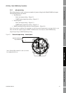
This chapter describes how to wire I/O for Model 2400S Analog transmitters.
Note: To wire I/O for Model 2400S PROFIBUS-DP and DeviceNet transmitters, see Chapter 4.
The 2400S Analog transmitter can be approved for Exe or Exi installation in Zone 1, or for
installation in Zone 2. If you are installing your transmitter in a hazardous area, be sure the transmitter
is approved for that area. It is the user’s responsibility to verify that the specific installation meets the
local and national safety requirements and electrical codes.
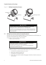
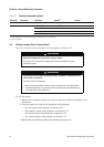
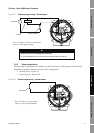
3.2 Moisture protection
When rotating or wiring the transmitter, guard against condensation or excessive moisture inside the
transmitter housing. Be sure that the conduit openings are completely sealed after all installation and
wiring procedures have been performed.
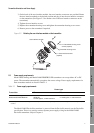
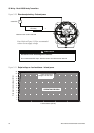
3.3 I/O options
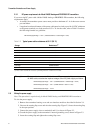
Table 3-1 lists the options for the transmitter’s two I/O channels. Before wiring Channel B, ensure
that you know how it will be configured. For information on configuring Channel B for function and
power, see the manual entitled Micro Motion
®
Model 2400S Transmitters with Analog Outputs:
Configuration and Use Manual.
CAUTION
Condensation or excessive moisture entering the transmitter could damage
the transmitter and result in measurement error or flowmeter failure.
To reduce the risk of measurement error or flowmeter failure:
• Do not mount the sensor so that the conduit openings on the transmitter point
upward.
• Ensure the integrity of gaskets and O-rings.
• Grease the O-rings every time the transmitter housing is opened and closed.
• Install drip legs on conduit or cable.
• Seal the conduit openings.
• Fully tighten all covers.